This thread has been locked.

If you have a related question, please click the "Ask a related question" button in the top right corner. The newly created question will be automatically linked to this question.

DRV8231A: Driver enters overcurrent mode

Part Number: DRV8231A
Other Parts Discussed in Thread: DRV8231,

Tool/software:

Hi Team,

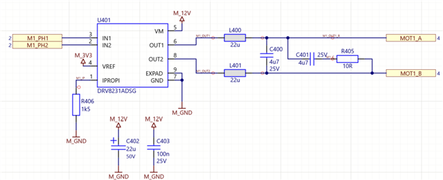
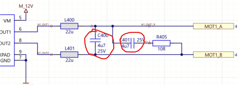
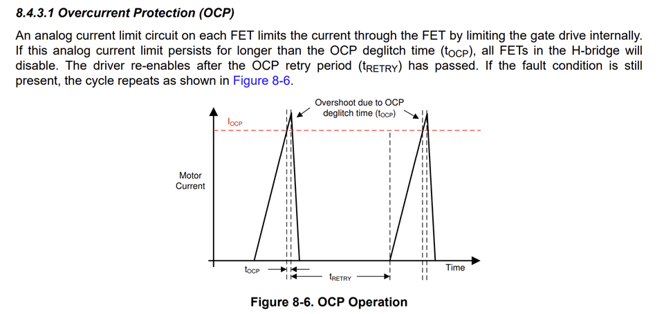
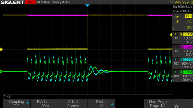
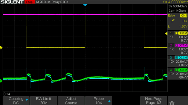
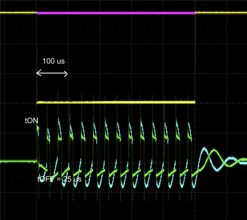
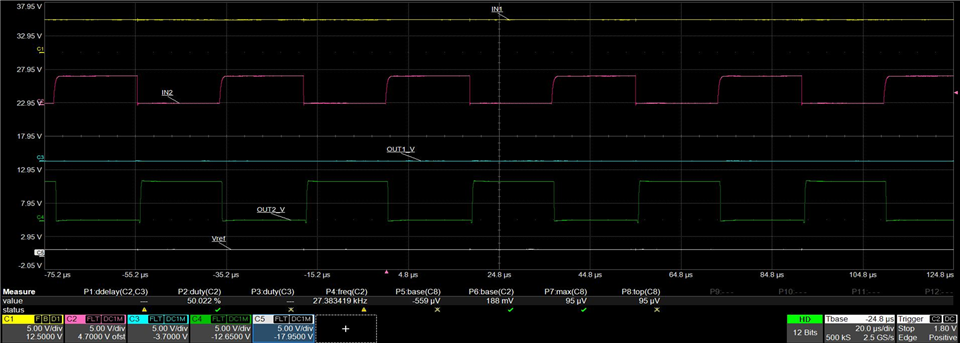
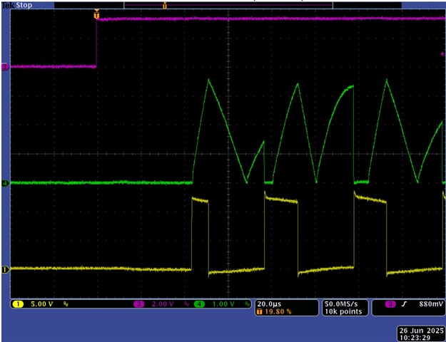
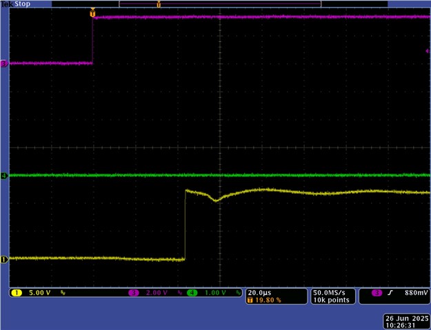
could you please check this circuit. Even if the motor is not connected the driver goes into overcurrent state. We set the input pins to 0 and 1 static and measured only a low voltage at the high side output of the driver with a waveform that shows a perodically switching off and on. We seemed this comes from the overcurrent state. The chip gets warm during test. Could you give us a hint? May be the ic is not the correct one DRV8231A but the DRV8231?

  • Hi Matthias,

    Thank you for your post and thanks for the schematic.

    RIPROPI = 1.5 kΩ and VREF = 3.3 V suggests ITRIP = 1.47 A. The IOCP of this device is 3.7 A MIN. 

    Even if the motor is not connected the driver goes into overcurrent state. We set the input pins to 0 and 1 static and measured only a low voltage at the high side output of the driver with a waveform that shows a perodically switching off and on.

    The output has two electrolytic capacitors - see below which may be potential suspects for this issue. Can you share the waveform capture that shows periodic switching off and on? I'd like to see if it has TOFF 25 μs signature or tRETRY 3 ms signature. 

    When the motor is connected the effect of the capacitors along with the L and R motor would be different. Please try with no capacitors on the outputs with no motor connected to see if the issue is resolved. 

    Regards, Murugavel 

  • Hi Murugavel,

    here is the figure of the waveform. The input signals are static but the output signals show pulsing waveform.

    yellow, pink = input pins
    blue, green = output measured at capacitor C400

    another figure of the waveform without any components connected at the output pins

  • Hi Matthias,

    Thanks for the waveforms. Based on the first waveform, I see the internal current regulation is kicking in - see below. I do not see an OCP signature which implies the current regulation is working.

    The initial charge current is triggering an ITRIP and tOFF for this device is 25 us. This cycle is repeating as long as the output is active. Essentially the capacitors are charging and discharging during tON and tOFF. After the motor is connected, the behavior of the LC of the motor would be completely different. Were the outputs normal with motor connected even with the capacitors? If we could also capture the IPROPI waveform along with the output it would be helpful. What happens to VM voltage input during this time? A capture of that would also be interesting. 

    The second waveform with both capacitors removed from the output pins does not show the tON and tOFF cycles anymore. However, the outputs are not making sense to me - I don't expect to see any bumps and not sure why both outputs are same while INx clearly has a square wave on one of them. Was this test done with multiple devices with same results? Thank you.

    See below example capture from past tests with this device. This was with no load at the output. The toggle rate for this test was 36.5 μs.   

    Regards, Murugavel 

  • Next figure shows the load current behavior without load. The green signal is the Iprop at 1k5 resistor. It breaks the output current when Iprop voltage = Vref 3.3V.


    pink = input signal
    yellow = output without load Vmot=12V
    green = signal at Iprop

    Next waveform shows the output but without current limitation, the Iprop resistor is 0R. the output reached 12V without load but with the 2 big capacitors 4µ7 for filtering.

    Question: There is a big filter against emc issues at the output, therefor a static control of the input signals trigger the current limit of the driver. But we want to control the motor by pwm in the range of 100kHz. Is this possible?

  • Hi Matthias,

    When you have a substantial capacitor filter to combat EMC at the output, this would be expected behavior when the motor load is not connected. However, as soon as you connect the motor the output network with the filter changes to an LRC circuit. Circuit response of an LRC would be different from a RC only at the output. I think with the motor connected you won't see this behavior because the L of the motor would slow down the di/dt in the network, assuming the motor L is in a couple of mH or less range.

    With motor connected it may be possible to drive with 100 kHz. You may have to calculate the LRC impedance behavior at 100 kHz and see if it has high enough impedance to limit the current flow to below the ITRIP value (and or OCP threshold). Did you get a chance to try this with the motor connected? Thank you. 

    Regards, Murugavel 

  • Hi Murugavel,

    I did the measurements again with a resistor load of 100R as a substitute of an original motor.

    Waveform with Riprop = 1k5 and load 100R

    Waveform with Riprop = 0R and load 100R

    As you can see in the figures, the current is somewhat higher, but the behavior is the same.

  • Hi Matthias,

    I did the measurements again with a resistor load of 100R as a substitute of an original motor.

    An 100 Ω resistor would not be a substitute for a BDC motor. Do we have the datasheet for the motor? I expect the motor resistance to be in a few ohms and also have inductance of the order of a few mH. In order to mimic a motor, the test load must be about the same resistance and inductance of the motor in series. Meaning a series L-R must be connected as the substitute test load. 

    Based on the RIPROPI = 1.5 kΩ in the schematic and VREF = 3.3 V, the ITRIP calculated value is 1.47 A. With a 12 V supply, 100 Ω will allow only 120 mA through it. I'd recommend to use like a 4 Ω resistor in series with a 1 mH inductor. The inductor must be low DCR, not more than 1 Ω. The truly meaningful test would be with the actual motor. BDC motors have high inrush current and when the speed picks up with have back EMF and current will settle down to a lower run current. This behavior cannot be replicated by an L-R in series. Thank you.

    Regards, Murugavel