This thread has been locked.

If you have a related question, please click the "Ask a related question" button in the top right corner. The newly created question will be automatically linked to this question.

DRV2700: Boost switching frequency and small signal bandwidth

Part Number: DRV2700
Other Parts Discussed in Thread: DRV8662

Tool/software:

Hello,

I would like to drive a 360nF Piezo between 0 and 100V, and the DRV2700 seems to be an adequate solution. I just had a few questions about its operation. 

- I wonder what happens if I want to drive the piezo at 1kHz. Will the driver be able to provide enough current or will its output be distorted?

- The driver's DS indicates a GBW product of 550kHz for the amplifier. Does this means the driver cannot exceed 10kHz with a 34.8dB gain ? What happens to the output in this case ?

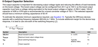
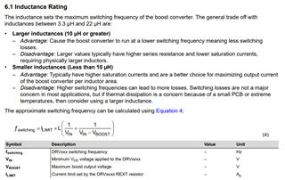
- I could only find information about the switching frequency in the configuration guide, but, if I'm not mistaken, the equation and the 1MHz value given in the guide don't fit. (see screenshots)

Thank you in advance for your help !

Regards,

Gaël

  • Hi Gaël,

    This combination of voltage, frequency, and load capacitance cannot be supported. See figure 6-12 of the datasheet. At 105V boost (0V to 100V), a 330nF load can be drive up to ~110Hz. If you're able to drive -50V to +50V, then the bandwidth, shown in figure 6-10, supports up to ~400Hz, but still pretty far from 1kHz. 

    For the gain bandwidth, you need to consider the loading on the output. That GBW value is No Load. It is best to consider the plots in the Typical Characteristics section of the datasheet. You will see the boost collapsing as you exceed the maximum loading capacity of the boost, this will be your limiting factor. The boost can drop to VDD.

    I'm not sure I understand your 3rd question. Equation 4 in that guide is for Fsw. Equation 10 is for the boost capacitance. I think each can be considered separately. I tried a few values, and they seem valid. The hysteretic boost will change the switching frequency based on the loading.

    Thanks!

  • Hi Kelly,

    Thank you for your reply !

    I wasn't aware that driving it between 0-100V instead of -50V/+5V0 would alter the bandwidth this much...

    I would like to understand a little bit more the behaviour of the amp+boost at higher frequency. Let's say I set the gain to 34.8dB and the boost in order to drive the piezo from 0 to 100V at frquencies up to 110Hz. If I understand correctly, the maximum amplitude will decrease as the frequency increases due to the limiting factors as presented in the datasheet (amp bandwidth, limited current, slew rate and thermal). 

    However what if the input went through a low pass filter so that as the frequency increases the driver isn't asked to drive as high as it does at 100Hz (10V at 1kHz and 1V at 10kHz for instance), what would happen then? Would it change anything to its response?

    Regarding the switching frequency, I wasn't refering to equation (10) but to the values presented in the table below. When I compute equation (4) I get a approximate switching frequency of 100kHz (Ilim = 1.9A, Vdd=5V, L=3.3µH and Vboost =105V) while the table in section 8 gives a typical switching frequency of 800kHz-1MHz. 

    I also considered that there whas an error in equation (4) and modified it as follows : Fsw=Ilimit*(1/Vin +1/(Vin-Vboost))/L. Is it correct ?

    Thank you again, pease let me know if anything is unclear.

    Regards

    Gaël

  • Hi Gaël,

    Ah, I see the issue. I missed it the first time and was subconsciously inverting the answer. You were close, but you can't just move L to the bottom, you need to invert the result. Equation 4 is wrong and actually calculating the time period, t = 1/Fsw.

    The units for Equation 4 are: A* ((V*s)/A) * (1/V) leaving only time (s=seconds) once A and V cancel out. 

    So using those values you get 1.19e-6 which converts to 839kHz, which falls in line with the values in the table under equation 10. 

    However what if the input went through a low pass filter so that as the frequency increases the driver isn't asked to drive as high as it does at 100Hz (10V at 1kHz and 1V at 10kHz for instance), what would happen then? Would it change anything to its response?

    You could try this.. It may be similar to the natural filter fall off in the gain plot. You're understanding is correct, the amplitude will decrease as you increase frequency. This is because the load is capacitive. Datasheet section 8.2.1.2.8 and the following few sections are helpful here.  

    FYI, you can also reference this tool for DRV8662. It will also apply to DRV2700. These parts are similar. 

    DRV8662-2665-2667_DESIGN_TOOL Calculation tool | TI.com

  • Hi Kelly,

    Many thanks for your explanations, they really clarified things for me! I've placed an order for the evaluation board, now I just need to test it.

    Thanks again,

    Gaël