Tool/software:
Thank you for your help.
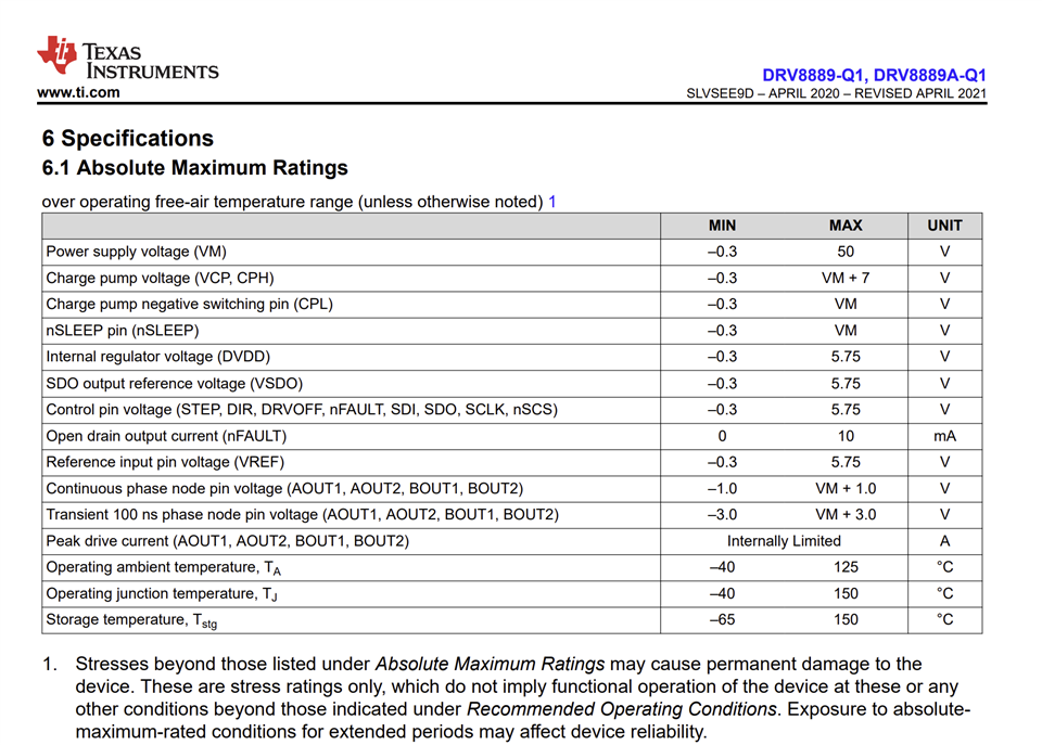
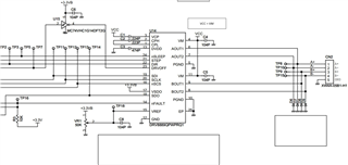
There have been three cases where circuits using the DRV8889-Q1 suddenly stopped working. The cause of these cases was a failure of the DRV8889-Q1. No output was obtained when commands were sent to the DRV8889 via SPI communication. Since it has been working fine up until now, we believe there is no problem with the communication process.
I am having trouble figuring out why the IC broke.
If there have been similar cases in the past, please let me know the cause and countermeasures.
(This text is written using Google Translate)