Tool/software:
Dear TI experts,
My customer tests their own PCB using DRV8706SQRHBRQ1.
They have an issue about test of diode freewheel mode. Please check the waveform below.

C1: IN1 (yellow), 0V
C2: IN2 (pink), 0V
C3: GH1 (blue), 0.7V
C4: Drive out1 (green), 0.7V
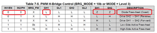
I check that device goes to diode freewheel mode if IN1 and IN2 are both 0V.

And GH1 output would be also 0V, So users can spin the motor to the direction whatever they want using their hands.
But as you see GH1 is not 0V, it is about 0.7V, so FET drive out is also 0.7V. So users cannot spin the motor to the direction what they want.
Is it normal operation? or do I miss something to make GH1 output 0V in diode freewheel mode?
Please check this issue. Thanks.
Best regards,
Chase