This thread has been locked.

If you have a related question, please click the "Ask a related question" button in the top right corner. The newly created question will be automatically linked to this question.

DRV8424: DRV8424 related issues

Part Number: DRV8424
Other Parts Discussed in Thread: DRV8825

Tool/software:

Hello,

The customer designs a stepper motor board for use in driving electronic expansion valves. The customer has encountered several issues, please help analyze them.
Generally, the motor phase resistance is around 3 ohms or lower, while the electronic expansion valve stepper motor phase resistance is around 100 ohms. The motor drive has chosen TI DRV8424, and the competing brand model is HR8825.

The DRV8424 driver settings are as follows:
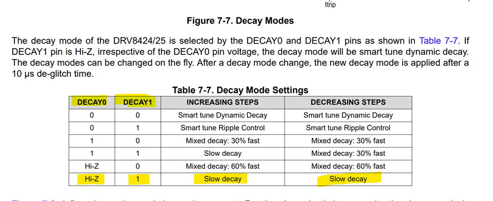
Chopping current 2000mA, slow decay in rising step, slow decay in falling step, TOFF set to 24us (tested 7us, 16us, 24us, 32us have little effect on the current waveform, but ultimately choose 24us to be consistent with competitors), step frequency 200pps.

The driver settings for HR8825 are as follows:
Chopping current 500mA, fully mixed attenuation, TOFF fixed 25us, step frequency 200pps.

Test situation: During the test, a 1 Ω resistor is connected in series to the coil to measure the voltage across the resistor and thus measure the coil current.


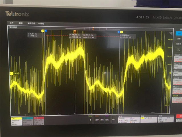
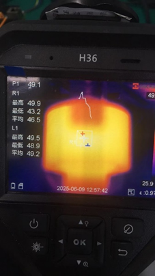
The HR8825 test current waveform and expansion valve temperature are shown in the following figure:
The DRV8424 test current waveform and expansion valve temperature are shown in the following figure:
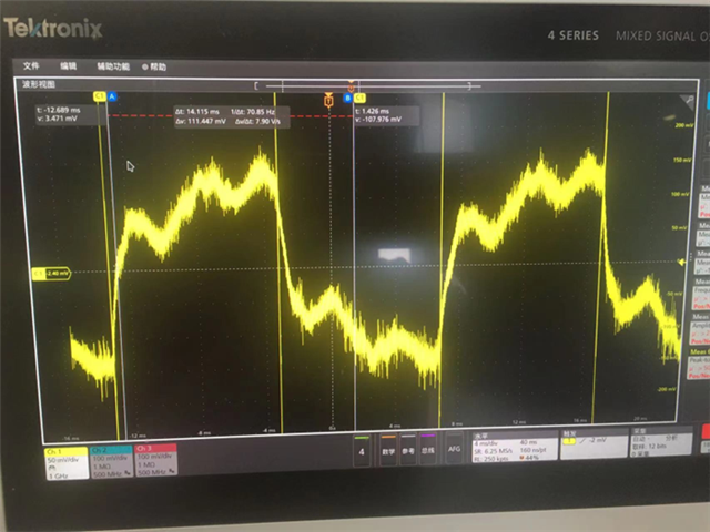
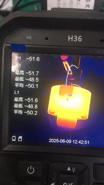
From the test results, it can be seen that the current waveform is basically consistent, and the TI chip has fewer spikes in the current waveform and a clean waveform. The temperature in the picture is the continuous operating temperature of the electronic expansion valve. The temperature of the expansion valve driven by HR8825 is 49 degrees Celsius, and the repeated test temperature is 45-46 degrees Celsius, taking the maximum value. The temperature of the expansion valve driven by DRV8424 reached 52 degrees Celsius. Excessive temperature can affect the lifespan of the motor.


The customer's questions are as follows:


1. Why does the chopping current of DRV8424 need to be set to 2000mA, that is, the VREF voltage needs to be around 2.6V to make the electronic expansion valve motor operate and form the above current waveform? When it is lower than the set 2000mA, the motor does not run or is powerless.


2. What is the difference between DRV8424 and HR8825 under the same attenuation mode and TOFF time settings, which can cause higher surface temperatures on the electronic valve? The data manual mentions that the current of the motor winding is regulated by the PWM control circuit, and the turn off time can also be adjusted. What is the PWM frequency and how to adjust it. What is the difference between two chips.


3. How to optimize the settings of the motor drive chip to match the application of high internal resistance motors such as electronic expansion valves?

Thanks!

  • Hi Jeno,

    Thank you for posting in this forum.

    The HR8825 is a copy cat version of the TI's much older and very popular in the past 10 years ago, stepper driver the DRV8825, FYI. 

    1. Why does the chopping current of DRV8424 need to be set to 2000mA, that is, the VREF voltage needs to be around 2.6V to make the electronic expansion valve motor operate and form the above current waveform? When it is lower than the set 2000mA, the motor does not run or is powerless.

    There seems to be some other issue. It could be the stepper motor has high DC resistance DCR, 100 Ω is very high and/or high inductance. What was the VM voltage used? I assume full-step mode based on the current waveform? Assuming VM = 12 V, the maximum current through the motor cannot exceed (Ohms law) 12/100 = 120 mA or if 24 V, 240 mA regardless of the Vref setting - the coil current will truncate at the calculated value and there cannot be any current regulation when the Vref is higher than for the supported current.  

    Could you please share the datasheet of the EEV motor? Please confirm if it is a bipolar stepper with 4-wires, coil diagram would be helpful to determine this.

    Test situation: During the test, a 1 Ω resistor is connected in series to the coil to measure the voltage across the resistor and thus measure the coil current.

    This should be fine, although using a non contact clamp-on current probe would be better. For example https://www.micsig.com/current%20probe/.

    2. What is the difference between DRV8424 and HR8825 under the same attenuation mode and TOFF time settings, which can cause higher surface temperatures on the electronic valve? The data manual mentions that the current of the motor winding is regulated by the PWM control circuit, and the turn off time can also be adjusted. What is the PWM frequency and how to adjust it. What is the difference between two chips.

    The DRV8424 uses fixed TOFF current regulation vs. the DRV8825 uses fixed PWM 30 kHz chopping current regulation. 

    3. How to optimize the settings of the motor drive chip to match the application of high internal resistance motors such as electronic expansion valves?

    For full-step mode with the DRV8424 I'd recommend using the slow decay setting. This will minimize heating.

    Regards, Murugavel 

  • Hello,

    VM=12V, Set the subdivision to 71% and run the current in full steps; The electronic expansion valve is indeed a four wire bipolar stepper motor.

    Please help recommend a newer model similar to 8825, suitable for driving electronic expansion valve applications (high internal resistance motors), and provide relevant settings. DRV8424 is good, but the customer wants to reduce the surface temperature of the electronic valve during operation.

    Thanks!

  • Hi Jeno,

    For full-steps mode the DR8424 must be set to slow decay for lowest motor heat. In addition choosing higher TOFF will reduce the heat - the customer is already using these settings, looks good. The DRV8424 utilizes the currently shipping latest stepper driving technology in our portfolio. 

    The DRV8424 driver settings are as follows:
    Chopping current 2000mA, slow decay in rising step, slow decay in falling step, TOFF set to 24us (tested 7us, 16us, 24us, 32us have little effect on the current waveform, but ultimately choose 24us to be consistent with competitors), step frequency 200pps.

    For VM = 12 V and stepper DCR 100 ohms, like I said previously the maximum current through the coils cannot exceed 12/100 = 120 mA regardless of the VREF setting. This also means there will be really no current regulation happening because the current will never exceed ITRIP is VREF is set to drive higher than 120 mA. But generally for this motor current regulation would not be necessary in full-step mode because of high DCR already. 

    Can the customer capture output current waveform with VREF set to 132 mV (0.132 V) and AOUT1 and AOUT2 waveforms and share with us? Thank you.

    Regards, Murugavel