This thread has been locked.

If you have a related question, please click the "Ask a related question" button in the top right corner. The newly created question will be automatically linked to this question.

DRV8702D-Q1EVM: Disabling PWM mode

Part Number: DRV8702D-Q1EVM
Other Parts Discussed in Thread: DRV8702-Q1EVM, , MSP-EXP430G2ET, DRV8702-Q1

Tool/software:

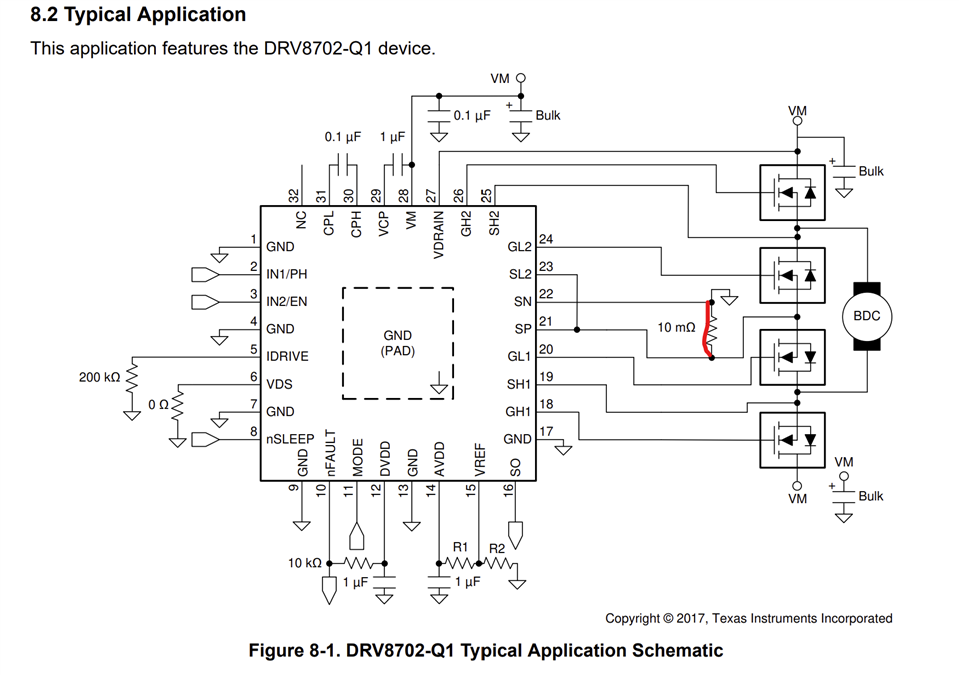
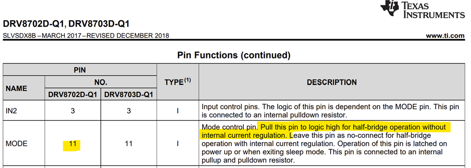
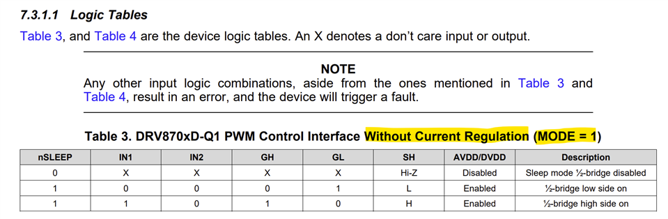
I found the DRV8702-Q1EVM board very suite for controlling inductive loads in general. Currently, I am controlling the board using a I/O pins from a MSP-EXP340G2ET board and the CCS software for flashing it. I need to drive inductive loads (tens of uH) with currents close to 12A and bipolar square waveform in the form ON: OFF : -ON: OFF, with no PWM during the ON periods. I was suggested that I can achieve it by disabling PWM option via programming, or by modifying the jumper connectors in the DRV board. My questions are: 1) Can I use the DRV8702-Q1EVM board to control the inductive load without PWM?

If yes, can you provide guidance/document links that explains how to disable it via software or via hardware?.

If not, what H-bridge driver ICs allows for PWM disabling? Is there an Evaluation board similar to the DRV8702D-Q1EVM?

Thanks

  • Hi Alfonso,

    If yes, can you provide guidance/document links that explains how to disable it via software or via hardware?.

    It appears you are looking for how to disable the on-chip current regulation PWM. Shorting the current sense resistor will disable the current chopping. SN and SP must be tied to GND. Please clarify if this was what you were looking for.

    1) Can I use the DRV8702-Q1EVM board to control the inductive load without PWM?

    Typically yes, as long as the inrush current does not exceed OCP threshold which is set by VDS. Thank you.

    Regards, Murugavel 

  • Thanks Murugavel for your reply. Yes, what I needed is to disable the PWM mode. I did it by using MODE=0 by connecting MODE to GND. I also set VREF to 3.3V or AVDD. In the end, I was able to control the board using the MSP-EXP430G2ET board. After disabling the MSP430 on the DRV board (by rewiring the J2 connector, moving the jumper to PUSH pin and connecting RST pin to GND), I did the following connections:

    • Wire the GND of both boards together
    • Set the DRV board to MODE=0 by connecting the MODE (J4 pin 11) to GDN.
    • Connect VREF (J4 pin 12) to 3.3V
    • Connect PH (J4 pin 2) to MSP board pin P.2.3
    • Connect EN (J4 pin 3) to MSP board pin P2.4
    • Connect nSLEEP (J4 pin 8) to MSP board P2.5
    • Connect 12VDC to DRV board H9 connector block
    • Connect the inductive load to H10 connector blockCoding and flashing the MCU using CCS IDE is great and there are plenty of examples to follow. I still need to augment the control code to output a trigger signal that can be used by a DAQ system, monitoring the protection signals available on the DRV8702-Q1 IC and ADC the H-bridge current monitoring signal at pin SO (this is why I can not implement your solution). Hopefully I will be able to flash the MSP430 on the DRV board using a 4-pin SBW cable I made. Thanks
  • Hi Alfonso,

    Yes, I didn't notice the MODE pin. This would be a better option to disable current regulation. However, per datasheet MODE pin must be logic high for disabling current regulation.

    Regards, Murugavel