This thread has been locked.

If you have a related question, please click the "Ask a related question" button in the top right corner. The newly created question will be automatically linked to this question.

DRV8323: DRV8323

Part Number: DRV8323

Tool/software:

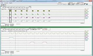
I am reading the SPI registers after power up and their contents do not seem to match the default value. I have captured the clock, data in, data out and NCS signals as shown in the attached document.

DRV8323S SPI Messages_0.docx

  • Additional info: The SDO has a pull up resistor of 3k3 yet the rise time of the signal is ~200ns which seems very long. The signal goes directly into an input port on a dsPIC33EP64MC202

  • Hi Michael,

    Your signals look pretty noisey?

    this first register read looks like a fault is triggered?

    did you make sure to following the SPI timing requirements from the datasheet?

    Regards,

    Yara

  • Received email from Yara Al Shami responding to my waveforms that I sent. I was not given the opportunity to respond to his questions directly however I would like to make the following comments:

    Noisy signals - the signals were measured with a common earth lead on the scope which would have introduced some perceived noise on the waveforms that were not actually there.

    First register suggests that a fault had occurred. This was not the case as the nFault pin was checked and this was at a high level.

    Finally the timing requirements were checked and found to be well within requirements.

    Not withstanding this these signals were measured directly after the supply power was applied and all registers should have had the default values which was not the case.

  • Hi Michael,

    If the fault register is not lining up with the nFAULT pin then you might have issues with you SPI read/write code. Just making sure but the device is out of sleep mode correct?

    Regards,

    Yara

  • I have checked that the device is out of sleep mode and that the SPI should be active.

  • Can you read the fault register? again if your fault register is saying there is a fault but the fault pin is not indicating that then there code be something wrong with your code you will have to debug.

    Regards,

    Yara 

  • I have eathed the scope probe to the 0V on the PCB and the signal is now clean. I am still getting an undervoltage lock out in register 0 yet there is no fault reported either in register 0 or on the nFault pin and the MOSFET outputs are switching when I enable the drive.

    Also as mentioned before the default register values are not loaded.

    I am at a loss to know what to do.

  • Apart from the UVLO in the Fault Status 1 register all seems to be working now. It appears that the Address bits were wrong. I have now corrected this and note that the default values seem to be okay. 

  • Hi Michael,

    Sounds like your issue has been resolved which is good to hear. 

    Are you able to clear the UVLO bit?

    Regards,

    Yara