This thread has been locked.

If you have a related question, please click the "Ask a related question" button in the top right corner. The newly created question will be automatically linked to this question.

DRV8323R: VDS monitor overcurrent fault

Part Number: DRV8323R
Other Parts Discussed in Thread: DRV8323

Tool/software:

Hi,

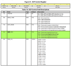
I am currently learning to use the DRV8323.When I input the three-channel complementary PWM waves to the DRV8323, the data read from the Fault Status Register was 0x0604, which means that the VDS overcurrent monitoring has been triggered.I have set the 0-3 bits of the OCP control register to 1111, which represents the maximum VDS voltage. However, the error still occurred. The voltage at the nFault pin has also dropped from 3.3V to 2V.

I'm sorry, I'm a rookie and currently I don't have any clear troubleshooting ideas. So, could anyone give me some hints and tell me where I should check?By the way, I only modified the value of the OCP register.

Thank you so much!it is very important to me.

Best wishes,

huan yin

  • Hi Huan,

    Have you read back the OCP register to confirm that what you are writing is being received?

    Have you configured the deglitch time?

    or the OCP_MODE?

    Regards,

    Yara

  • Hi,Yara

    I did re-read the OCP registers and made sure that the VCP voltage was set to the maximum. However, I did not modify the deglitch time and OCP_mode, as they remained at their default values.May I also set the "deglitch time" to the maximum?Should the OCP_MODE be configured as 10 or 11?

    Thank you for your reply. This is very important to me.

    Best wishes 

    huan yin

  • Let me add that now I have configured the OCP register as 0x2B7F: The VDS setting is at the maximum level of 1.88V; the overcurrent glitch elimination time is 8us; and the dead time is 400ns.However, the Fault Status Register remains at 0x0604.

  • Hi Huan,

    Is this only happening on start up? are you able to clear the fault or does the fault keep coming back? What is the state of the fault pin?

    Regards,

    Yara

  • Hi Yara,

    Every time I input PWM, an overcurrent occurs and the fault pin also goes low.I think this might be related to my hardware. Because I observed a phenomenon: when I turned on the 12V power supply (without performing any other operations), the GHA pin would output 12V. I think this seems abnormal. Could you please tell me if this is correct?

    In fact, I have already turned off the overcurrent monitoring (OCP_MODE = 11b).

    Best wishes,

    huan yin

  • Sorry, there was an error in the previous statement. After turning on the 12V power supply and activating the ENABLE pin, I observed that the GHA pin was at 4.5V. Based on this, I connected the SPI pins (without conducting any communication), and observed that the GHA pin was at 12V.

  • To be precise, after connecting the SCK pin of SPI, the voltage of GHA will change to 12V. There is a 100Ω resistor between the SCK pin and the SCLK pin of the DRV8323.

  • Hi Huan Yin,

    Are you using the EVM or your own design? If it is your own design can you share the schematic?

    When GHA outputs 12V what is the state of the INHA and INLA?

    When you say 

    There is a 100Ω resistor between the SCK pin and the SCLK pin of the DRV8323

    do you mean between the MCU and the DRV?

    Regards,

    Yara

  • Hi,Yara

    I am using a custom-designed driver board, and the schematic diagram is attached.

    The MCU and DRV are connected via a DuPont cable.

    If there are any design issues with the schematic diagram, please let me know. This is very important to me.Thank you so much for your assistance.

    Best wishes,

    huan yin

  • Hi Huan,

    your schematic looks good, I dont really notice anything out of place.

    This is the point where you are using a dupoint cable correct to connect to the mcu?

    Are you connecting the MCU GND to the DRV GND? maybe there is a large GND difference that could be causing some SPI miscommunication to happen?

    Regards,

    Yara

  • Hi Yara,

    Yes, this position is where the MCU and DRV are connected. I have connected the GND interfaces of the MCU and DRV, but the situation has not improved.

    Best wishes,

    huan yin

  • Hi Huan,

    I know on one of the other threads you mentioned the SPI waveforms didn't look correct after switching the IC, have you been able to capture said waveforms yet?

    Regards,

    Yara

  • Hi Yara,

    The issue regarding the SPI waveform has been resolved. The cause of the error seems to be the voltage difference between the MCU and the DRV driver board, which led to SPI communication interference. Now the SPI communication waveform is completely correct. However, the voltages of GHA and GHC remained abnormal, being 12.4V and 16.7V respectively.

    Currently, the cables I'm connected to consist of 7 wires: VCC and GND between the MCU and the DRV driver board, the ENABLE line of the DRV, and four SPI lines.It is worth noting that when I pulled the ENABLE pin low, the abnormal voltage phenomenon did not occur. This seems to indicate that the driver board is not damaged?Perhaps you could offer me some troubleshooting ideas. This is very important to me.

    Thank you so much for your assistance.

    Bset wishes,

    huan yin 

  • Hi Huan Yin,

    Can you provide waveforms of GHx with respect to SHx, and SHx to GND?

    It makes sense that pulling ENABLE low makes the issue go away since you are powering down the device.

    Regards,

    Yara

  • Hi Yara,

    After testing, the voltages of GHx and SHx are the same, and the MCU and DRV are already connected to the same ground.

    The waveform measured by the oscilloscope is as follows (C1 is GHA, C2 is SHA, C3 is GND)

    Thank you so much for your assistance.

    Bset wishes,

    huan yin 

  • To add, the voltage of GHC is 16.75V, and the voltage of SHC is 12V.

  • Can you provide the waveforms as you're attempting to drive your motor? Are any faults being triggered?