This thread has been locked.

If you have a related question, please click the "Ask a related question" button in the top right corner. The newly created question will be automatically linked to this question.

DRV8262: DRV8262EVM: DRV8262 reverse EMF and protection for brushed DC motor application

Part Number: DRV8262
Other Parts Discussed in Thread: , DRV8263-Q1

Tool/software:

Hello, 

I am trying to use DRV8262 for brushed DC motor application with single H-bridge. 

My motor will run at DC (not PWM) with VM voltage of 35V and motor current about 3A. Depending on enable signals of DRV8262, motor will stop/forward/reverse, but all DC. 

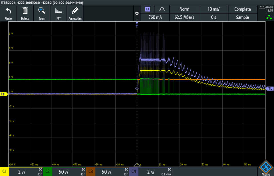
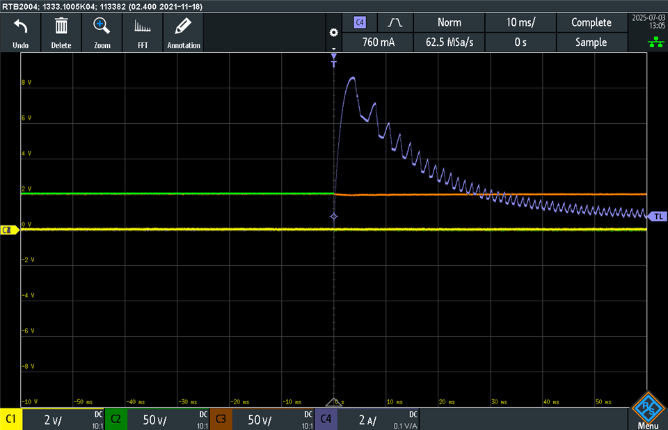
I don't see any Back EMF mitigation electronics in the DRV8262EVM. Do you have any suggestion as to which electronics need to be included to suppress BEMF in addition to what EVM has? I don't see DRV8262 itself regulating Back EMF.. I don't have good number of what BEMF voltage will be and I really need to test it out in the lab. Not sure if it's safe to use DRV8262 to drive the motor with above spec. It would be great if anyone can confirm. Basically, I am not sure if I need to include additional circuits (i.e., back emf shunt regulator or regen resistor) not to damage DRV8262EVM. I would also need to know when it comes to the custom design. 

Please let me know if you need additional information from my side. Thank you!

  • Hi Jake,

    Thanks once again for reaching out to us via this forum.

    All our brushed DC BDC motor drivers with integrated FETs are designed to drive BDC motors directly connected to them. The parasitic body diodes on the internal power FETs will mitigate the BEMF visible on OUTx during the drive transition dead time. No additional external BEMF mitigation electronics are needed generally. 

    See below oscilloscope captures using a DRV8262EVM, using one of the two H-Bridges to drive a 48 V BDC motor. Blue trace is the actual motor current, yellow trace is the IPROPI1 voltage, green trace is OUT1 voltage and the orange trace is OUT2 voltage. VM supply is a 48 V, high current battery pack source. The two wires of the BDC motor are directly connected to the EVM terminal OUT1 and OUT2 points. 

    There are two ways to drive the motor using the DRV8262, with direct DC control with no PWM input to IN1 or IN2. 

    1. Using the on-chip current regulation feature to mitigate the inrush current during motor startup. In the capture you can see the OUT voltage is chopped to achieve output current regulation. TOFF was set at 16 μs. The PWM chopping stops once the motor picks up speed and its BEMF counter balances the inrush current to a steady state value. While current regulation mitigates the startup current effectively because of reduced startup current the motor does not accelerate as fast as it could. 
    2. Disabling the on-chip current regulation feature by connecting IPROPI1 to GND to allow the entire peak inrush current during motor startup. Because the entire inrush current is allowed, the motor accelerates to steady state speed as fast as it could. Ensure the inrush peak does not exceed IOCP threshold, which will trigger an OCP trip to protect the FETs if > IOCP for > tOCP. If single bridge cannot support the desired peak inrush, both the H-Bridges must be connected in parallel and driven in Single H-Bridge mode as shown in the datasheet. The upcoming new product the DRV8263-Q1 could also be considered. 

    With current regulation, RIPROPI 3.3 kΩ (built in the EVM) and VREF = 3.3 V to limit the inrush current to around 5 A:

    Current regulation disabled, inrush current is not limited:

    Regards, Murugavel 

  • All our brushed DC BDC motor drivers with integrated FETs are designed to drive BDC motors directly connected to them. The parasitic body diodes on the internal power FETs will mitigate the BEMF visible on OUTx during the drive transition dead time. No additional external BEMF mitigation electronics are needed generally

    My understanding of BEMF is that BEMF will be generated either when motor stops or change the direction. Are you saying in the deadtime, parasitic body diode will block the BEMF flowing back to the source? I believe those are NMOS so shouldn't it be conducting as cathode of diode is on drain side of transistor even if transistors are off state or High-Z state? I think I may be misunderstanding something but please correct me if I am wrong. I have done design utilizing TI's gate driver ICs and external transistors, but I had to design BEMF regulator electronics separately near the source side. I did not understand why this integrated IC can mitigate BEMF.. 

    Using the on-chip current regulation feature to mitigate the inrush current during motor startup. In the capture you can see the OUT voltage is chopped to achieve output current regulation. TOFF was set at 16 μs. The PWM chopping stops once the motor picks up speed and its BEMF counter balances the inrush current to a steady state value. While current regulation mitigates the startup current effectively because of reduced startup current the motor does not accelerate as fast as it could. 

    Also, I am not understanding what you mean by BEMF counter balances the inrush current to a steady state value.. 

  • Hi Jake,

    My understanding of BEMF is that BEMF will be generated either when motor stops or change the direction. Are you saying in the deadtime, parasitic body diode will block the BEMF flowing back to the source? I believe those are NMOS so shouldn't it be conducting as cathode of diode is on drain side of transistor even if transistors are off state or High-Z state? I think I may be misunderstanding something but please correct me if I am wrong.

    BEMF will be generated by the BDC motor as long as it is spinning whether while being driven - in this case BEMF opposes the applied voltage - or - while the motor is mechanically spun by external means. When the motor is stopped (stand still) or at transition point of the direction change where its physical motion is 0, its BEMF will be 0. 

    The formula for back EMF in a brushed DC motor is Eb = Kω, where Eb is the back EMF, K is the back EMF constant of the motor, and ω is the angular velocity of the motor. When the motor is in standstill ω = 0, so Eb = 0. BEMF can also be expressed as Eb = VM - IaRa, where VM is the applied voltage, Ia is the armature current, and Ra is the armature resistance.

    During dead time when the coil voltage is switched off there will be an inductive kick back (not BEMF) which may be > VM. During this time the body diode will conduct and mitigate the inductive kick back. This is why the OUTx pins are specified with the highlighted absolute max. specifications - see below. This is more of an inductive kickback rather than BEMF because of switching. I'll recall this phrase "The parasitic body diodes on the internal power FETs will mitigate the BEMF visible on OUTx during the drive transition dead time.". for accuracy sake - not BEMF in this instance.  

    That said, when the VM supply input is unplugged while the motor is running at full speed, the BEMF generated by the motor would be conducted to VM and GND via the body diodes, positive side via one of the HS-FETs depending on the motor direction and negative side to ground via one of the LS-FETs. This generated BEMF would be available on the VM rail until the motor comes to a stop.

    See below capture, triggered with nFAULT falling edge after UVLO, when VM was unplugged while the motor was running at full speed with 48 V supply. Yellow trace is the IPROPI1 voltage showing motor current, orange trace is the VM - see a dip? cursor 2, this is when VM was unplugged, green trace is nFAULT which goes low when VM < UVLO ~ 4.3 V. Notice the BEMF voltage appears on the VM rail for at least 300 ms? It is declining in amplitude as the motor slows down, due to frictional loss of rotational energy. It becomes 0 when the motor goes to standstill.  

    If you were to stop the motor instantly after the supply is unplugged the BEMF will decline much faster because the motor slows down to 0 speed much faster. If you were to brake a full speed motor after turning off the drive you'll have to make sure all the energy dump can be handled by the FETs that is in the braking circuit path. One mitigation would be to ramp down the speed gently with a decreasing PWM duty cycle from 100 % to 0. 

    The same is true for instant reversal of a running motor. For direction change the bridge should be reversed. The drive energy required would have to stop the motor in the current direction and then reverse it. During this time BEMF energy from the current direction would be absorbed by the FETs. See below capture of direction reversal. Blue trace is the actual motor current, yellow trace is the IPROPI1 voltage, green trace is OUT1 voltage and the orange trace is OUT2 voltage. VM supply is a 48 V, high current battery pack source. The two wires of the BDC motor are directly connected to the EVM terminal OUT1 and OUT2 points. VREF = 3.3 V.

    Direction change forward to reverse:

    Direction change reverse to forward:

    The on-chip current regulation mitigates the extreme case of high current peak due to counteracting the BEMF of the motor running in one direction. With current regulation disabled it is not possible to perform this on-the-fly direction reversal because the resulting current peak will trigger an OCP. Only a stop wait and reverse is possible. I verified this to be true. The current peak reached about 9 A which is > IOCP 8 A MIN specification. 

    Regards, Murugavel 


  • During dead time when the coil voltage is switched off there will be an inductive kick back (not BEMF) which may be > VM. During this time the body diode will conduct and mitigate the inductive kick back. This is why the OUTx pins are specified with the highlighted absolute max. specifications - see below. This is more of an inductive kickback rather than BEMF because of switching. I'll recall this phrase "The parasitic body diodes on the internal power FETs will mitigate the BEMF visible on OUTx during the drive transition dead time.". for accuracy sake - not BEMF in this instance. 

    Thank you so much for your detail explanation. One last question, how do I make sure that inductive kick back energy is lower than maximum rated voltage show in the datasheet? (VM+3V and VM+1V) 

  • Hi Jake,

    One last question, how do I make sure that inductive kick back energy is lower than maximum rated voltage show in the datasheet? (VM+3V and VM+1V) 

    The short answer is, in majority of the BDC motor drive use cases you won't have to do anything. The body diode would automatically limit the voltage above VM to its VF and voltage below GND to its  -VF which would be ≤ 1 V, typically.

    The voltage induced in an inductor VL = L * (di/dt), 'di/dt' is the rate of change of current through the coil with respect to time and L is its inductance. The induced voltage is determined by how quickly the current is changing, as well as the coil's inductance. A larger inductance or a faster change in current will result in a higher induced voltage. When the current through the motor inductance is switched on or off, the di/dt would be very high, especially 'dt' being a fast fall time or rise time of the switching. The open circuit voltage induced is usually very high compared to the VM voltage applied, however it does not have a lot of energy in a typical brushed motors whose inductance is < 5 mH with resistance 5 to 10 Ω. When it is loaded the voltage would drop significantly. The positive peaks would be conducted by the HS-FET body diode to VM rail and the negative peaks would be conducted by the LS-FET body diode. The voltage on OUT1 would be VM + VF and on OUT2 would be OUT2 would be GND - VF, VF is the forward drop of the body diode which would be ≤ 1 V for currents in the range of rated current (same as FET rated current) through it. 

    If for some reason, for example very high inductance of the motor 10's of mH the kick back energy, hence current via the body diodes, may get much higher resulting in VF > 1 V. I have never seen this happen with typical BDC motors that were used to drive with this driver. In this case, external Schottky diodes with higher rated current can be connected in parallel to all the body diodes on OUT1 and OUT2 to limit the rapid voltage excursion. 

    If these MOSFETs were a BJT or an IGBT that does not have inherent body diodes the induced voltage would be 100's if not 1000's momentarily killing the silicon instantly. This is why such designs would have external mandatory freewheeling diodes to take care of this situation in such applications. 


    Regards, Murugavel