This thread has been locked.

If you have a related question, please click the "Ask a related question" button in the top right corner. The newly created question will be automatically linked to this question.

DRV8874: Fault signal, normal operation problem after power re-apply

Part Number: DRV8874
Other Parts Discussed in Thread: DRV8873, DRV8243-Q1

Tool/software:

Hello
It was a circuit that was working normally, but a problem occurred after changing the motor.
For example, in PH/EN mode, if EN=1, PH=0 is given, it works normally
But if PH=1 is changed or EN is changed to 0 and then changed back to 1, it does not work normally.
If you try the same thing again on the existing motor, it works normally.
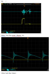
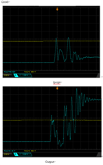
When a problem occurs, it returns to high for a short time at 'fault = 0' and then becomes low again. However, if you turn the system off and on again, it works normally.

I tried GND, 20K ohm, and Hi-z for IMODE, and Low, High, and Hi-z for PMODE. I also tried changing Ripropi to 0, 6.8K, and 13K.
Even if Ripropi is installed at 0 ohm and VREF is given at 3.3V, it does not improve.
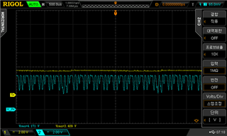
When the direction is changed as above, if the motor does not rotate normally, a small high-frequency sound is heard. If I turn the power supply off and on, it works normally.
It seems that there is a capacitor of unknown capacity inside the replaced motor. Could this be the problem?
Please advise.

  • I thought it was due to the initial inrush current caused by the capacitor, so I connected a 10 ohm resistor to OUT1 and 2, and it was resolved. So I connected a resistor corresponding to 400mA of Ripropi current limiting again, and the problem occurred again.

  • Hello,

    If I understand correctly the nFAULT pin is getting pulled low, if this is the case can a capture with the motor that is having an issue be provided with the output current, EN pin, OUT2 or OUT1, and nFAULT with a trigger on nFAULT going low? 

    If the OUTPUT current is exceeding 6A or greater than 3us then the fault is most likely an OCP fault. In this case can the capture provided include the output current, IPROPI voltage (as close to the pin as possible), VREF voltage, and nFAULT with a trigger on the nFAULT signal going low?

    Also, if the schematic can be provided that would be helpful as well.

    Regards,

    Joshua

  • thank you 

    The normal waveform is the waveform when an inductor of about 10mH is connected in series. The current waveform on the last page is not exact because I changed many resistors, but it is probably 6.8K ohm resistor. As you advised, it seems to be a problem due to the initial peak current. Can you recommend a better IC?

  • In all the captures provided I see the output channel has voltage as the units so I want to make sure, is this the current through the load? If it is not, if you have a current probe can the current be captured with the current probe so the load current can be analyzed easier?

    I am a bit concerned with the output waveform in the good capture. The output voltage appears to be dropping out as the voltage rises, can a capture including VM and the OUTx voltage be provided for this case? I want to make sure that VM is not dipping when the OUTx voltage is rising since this could also be leading to issues with driving the motor.

    In the good capture, assuming that the IPROPI resistor is still 1kohm, the current is getting close to the OCP threshold. If you would like to try a different device I would recommend the DRV8873 with the better alternative being the DRV8243-Q1 but this is automotive qualified so not sure if a -Q1 device interests you.

    Regards,

    Joshua