This thread has been locked.

If you have a related question, please click the "Ask a related question" button in the top right corner. The newly created question will be automatically linked to this question.

DRV8316: Current Sense Amplifier Offset Correction

Part Number: DRV8316

Tool/software:

Hello Ti,

I have two questions: 

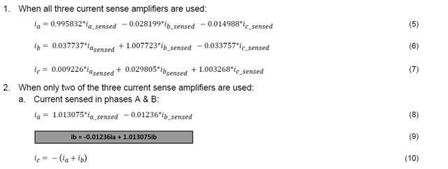
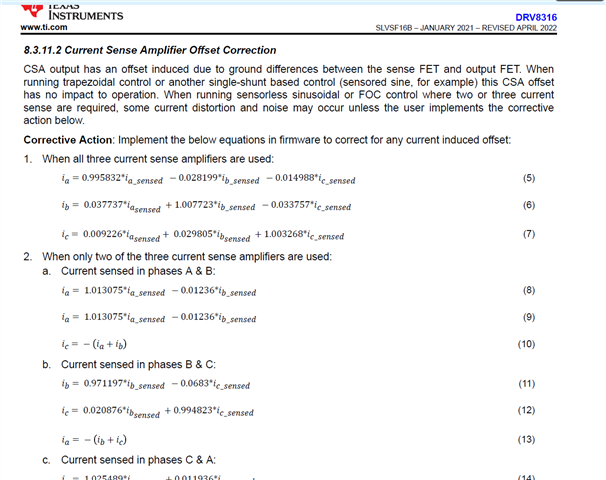
1-I see in the datasheet of the DRV8316 [SLVSF16B – JANUARY 2021 – REVISED APRIL 2022] at section 8.3.11.2 Current Sense Amplifier Offset Correction, the equations 8,9 are wrong and in other thread i see correction but i need to make sure it is correct as it doesn't make sense that Ia = Ib 

the correction is provided in this thread  https://e2e.ti.com/support/motor-drivers-group/motor-drivers/f/motor-drivers-forum/1505676/drv8316-mistake-in-current-sense-formulas 

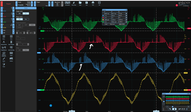
2-At some instances the drv8316 current senses voltage on ISENx is weird and has large non real zero gaps while it is okay at other instances , please check the below images for difference in signals :

the CSA gain configured is 0.6V/A

Noting that the bottom yellow signal is the actual phase_a current provided to the motor and the top three are the ISENSE_a,b,c

Regards

  • Hi Shehab,

    1. You're right about the equations. I think they should look like this

    2. What PWM mode are you using? and what is the duty cycle of your pwm signals? It might be a good start to try out different PWM duty cycles or heavy vs light loads or lower RPM. This doesn't necessarily look like a hardware failure but something does seem off in the timing of the second waveform you provided .

    Regards,

    Yara

  • Hello Yara,

    2. What PWM mode are you using? and what is the duty cycle of your pwm signals? It might be a good start to try out different PWM duty cycles or heavy vs light loads or lower RPM. This doesn't necessarily look like a hardware failure but something does seem off in the timing of the second waveform you provided .

    I am using PWM_Mode 0, as you can see in waveform 1 it looks good which is at lower speed, so what is my problem here and why does duty cycle matter in the sensed current as in both waveforms the actual phase current (OUT_A sensed by current clamp) is sinusoidal ?

    in other words, At what time exactly the phase current is measured and converted to corresponding voltage signal? is this related to the pwm duty cycle or the actual current passing through the motor phase?

  • Hi Shehab,

    CSA only measures current during PWM "off-time" when the low-side FET is on, the higher the duty cycle the smaller the window for the CSA to sample.

    Regards,

    Yara

  • Hello Yara,

    Thanks for your reply, but don't we have any thing to do to sample also during the "on-time"? as sampling only in off-time will make us lose some duty% (e.g limit of 98% to have low windows for sampling)

    Regards,

  • Hi Shehab, 

    Pretty much all our drivers implement low side current sense. You could implement in-line current sense with INA240 and that would sample in-line with the motor phase so duty cycle wouldn't really play a part.

    Have you tested your system with a lower duty cycle? have you confirmed that the issue goes away at lower duty cycles?

    Regards,

    Yara

  • Hi Yara,

    Yes issue was mainly due to higher duty cycles.

    Thank you,

    Shehab