Other Parts Discussed in Thread: TPS1HTC30-Q1
Tool/software:
Hello,
I am using the DRV3946-Q1 in an application with contactors that have a built in economizer. I am seeing some weird behaviors where the driver IC gives an over-current error on the low side.
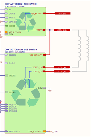
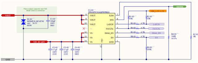
High side switch: TPS1HTC30-Q1
- Always on during the test
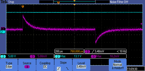
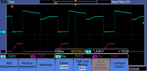
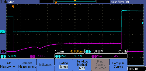
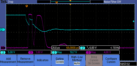
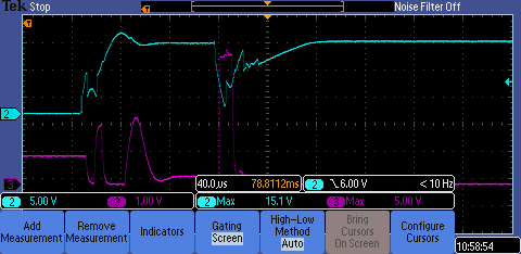
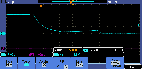
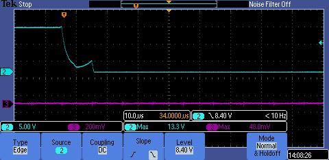
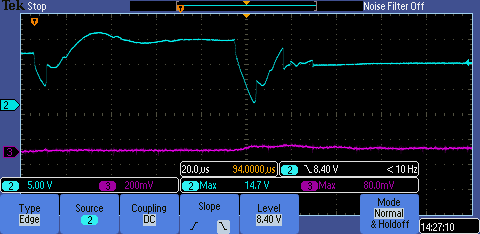
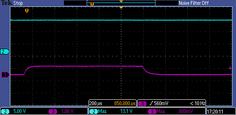
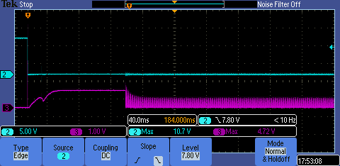
- FAULTn signal goes low for ~40us when the low side fault trips, but it self-recovers (it does not open the high side switch)
- The LATCH is pulled high so expect a fault to latch the high side switch off and require toggling the LATCH to reenable -- but despite seeing FAULTn go low, don't see the switch turn off
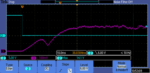
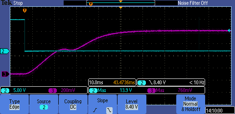
- The current measured on the high side switch at it's peak is 10.5A
- The high side side switch over-current limit is expected to be 16A (R_ILIM = 0 Ohm to GND)
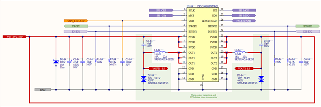
Low side switch: DRV3946-Q1
- We've tried changing the peak and hold current limits to 2A hold, 4A peak up to their maximum setting 0xFF
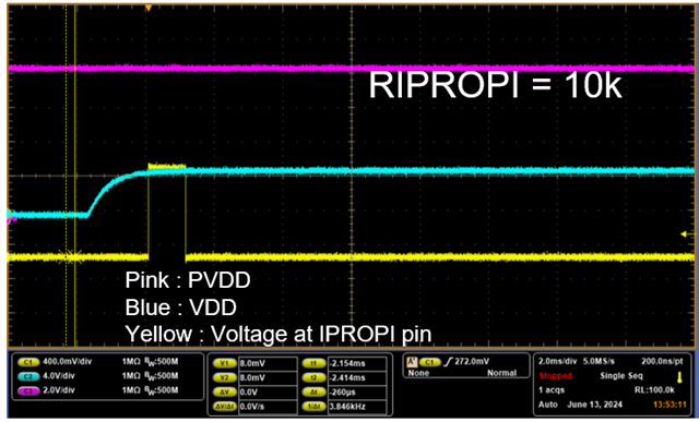
- The IPROPIx resistors are 10.7kOhm
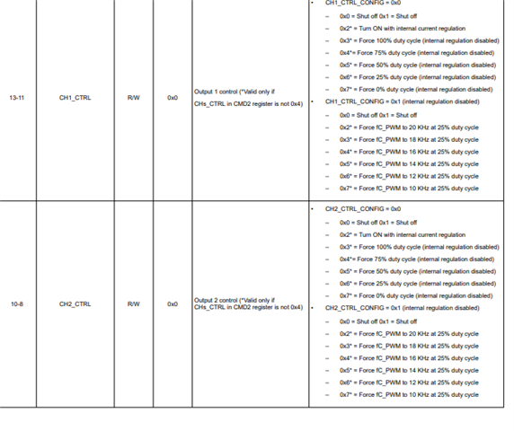
- We have an external RC filter from this pin to our MCU for measuring analog voltage which is 4.7kOhm + 470nF
- With this external RC filter, we found the DRV measured resistance to be 4.7kOhm
- We tried adjusting or removing the external RC the DRV measures the expected resistance (10.7kOhm)
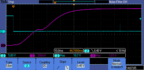
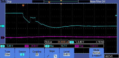
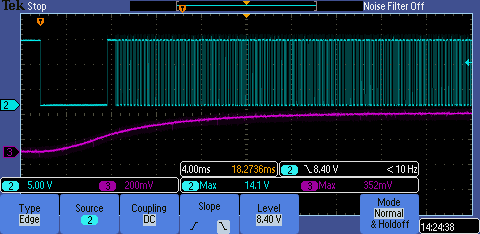
- With the external RC on IPROPIx (DRV reported resistance = 4.7k), we occasionally get an over-current trip when driving a contactor with a built-in economizer
- Without the external RC on IPROPIx (DRV reported resistance = 10.7k), we repeatedly get an over-current trip when driving a contactor with a built-in economizer
- When trying on a contactor without an economizer the circuit works as expected
Is there a recommended configuration for the DRV3946-Q1 when using it with contactors which have an economizer? Any ideas why having the DRV detect the correct resistance result in more over-current faults? Why is the DRV reporting over-current at all if the measured current (measured on the high side switch) is < 11A?
Thank you for any help you can provide.