Tool/software:
Hi Teams,
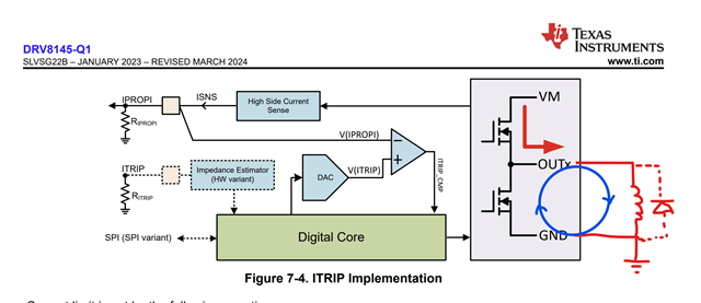
Please help to check DRV8145 inductive load current re-circulates questions as following, thanks.
1. Will the current flow in the direction of D1?
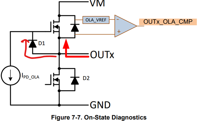
2. Is there a risk of IC damage if reverse current flows through the HS body diode?