


Other Parts Discussed in Thread: MOTORWARE, LAUNCHXL-F28069M,
Tool/software:
Hello
I am trying to spin a T-MOTOR MN4004-25 300kV BLDC motor with a Launchxl-F28069M and BOOSTXL-DRV8305EVM using MotorWare (Last release).
When running lab 2c, The motor appears to be stable and vibration free during EST RampUp and Ls state. After identification, the motor is rough running (vibrates intensly) unless moved and or handled in some specific ways at which point it becomes stable again. Sometimes the vibration is so intense that the OVP on my lab power supply shuts off power. I have probed I_SENSE A on the boostxl using an oscilloscope.
Phase A current (voltage drop across shunt resistor R4 for Phase A. amplified and sent out to the launchxl on ISENSEA pin) during identification of RampUp: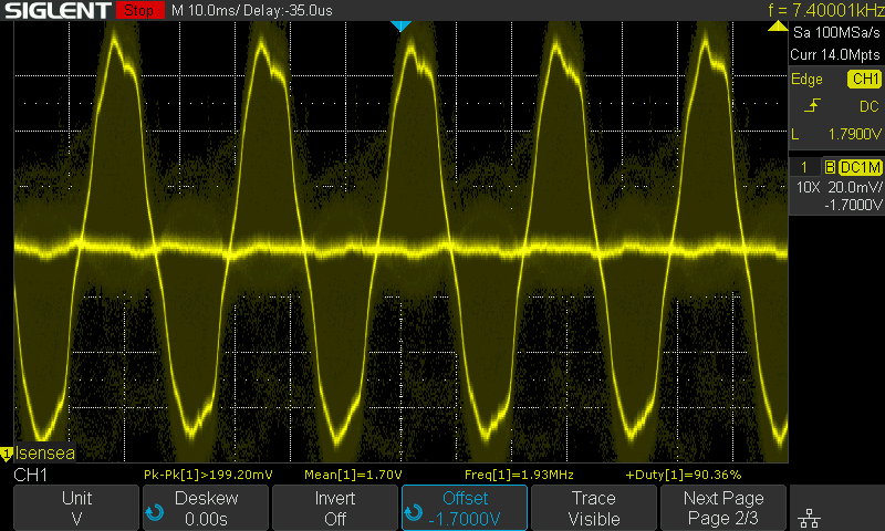
During Rated Flux: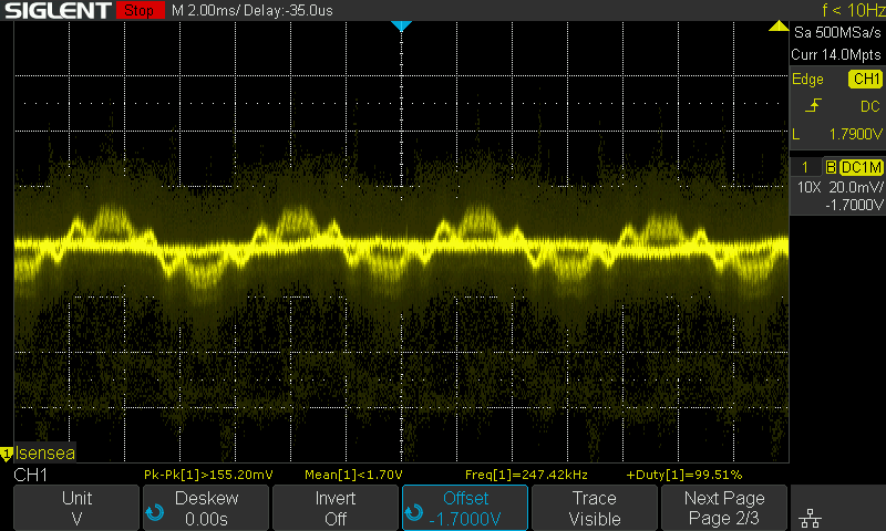
During Ls: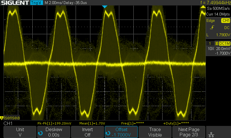
The last graph is closer to what I expect from a phase current for a bldc motor (looks close in MATLAB simulation for this hardware setup)
However, after identification is done, when running the motor, it is very rough and vibrates excessively unless rotated or handled in some way (there is an irremovable bearing on the shaft of the motor, perhaps CG changing has some effect on the torque or speed PI controllers. maybe FAST too?)
after identification and when running rough, the current looks as follows: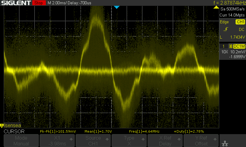
While it is smooth running after ID: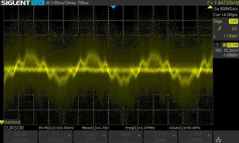
the last two graphs also apply to Lab 3b, when the motor runs with no identification.
I believe this issue cannot be a motor parameter issue (why would it run smoothly when moved/handled after identification?) so maybe it is a control loop (speed PI or torque PI) issue or an issue with the FAST estimator? I have checked connections.
motor parameters used:
#elif (USER_MOTOR == TMotor_Antigravity_4004_300kv)
#define USER_MOTOR_TYPE MOTOR_Type_Pm
#define USER_MOTOR_NUM_POLE_PAIRS (12)
#define USER_MOTOR_Rr (NULL)
#define USER_MOTOR_Rs (0.2621875555)
#define USER_MOTOR_Ls_d (0.000160895237)
#define USER_MOTOR_Ls_q (0.000160895237)
#define USER_MOTOR_RATED_FLUX (0.00984939188)
#define USER_MOTOR_MAGNETIZING_CURRENT (NULL)
#define USER_MOTOR_RES_EST_CURRENT (1.0)
#define USER_MOTOR_IND_EST_CURRENT (-1.0)
#define USER_MOTOR_MAX_CURRENT (4.0)
#define USER_MOTOR_FLUX_EST_FREQ_Hz (150)
Note that I also used EST_FREQ 100 and 120 Hz with no apparent difference (100 hz appeared to be even less stable)
Motor parameters for some other successful project using the same motor and hardware kit:
https://github.com/open-dynamic-robot-initiative/user_config_f28069m_drv8305/blob/8ab4879222142fd232037e8d2e30d248ecb7b674/user_j1.h
The values given by the identification process in Lab 2C closely resemble the values in the project link above.
Using default hardware values for the BOOSTXL-DRV8305EVM and LAUNCHXL-F28069M
I would appreciate your advice on how to proceed with diagnosing this issue

