This thread has been locked.

If you have a related question, please click the "Ask a related question" button in the top right corner. The newly created question will be automatically linked to this question.

MCT8316A: Value of Speed Pin during Power On

Part Number: MCT8316A
Other Parts Discussed in Thread: MCT8329A

Tool/software:

Hello

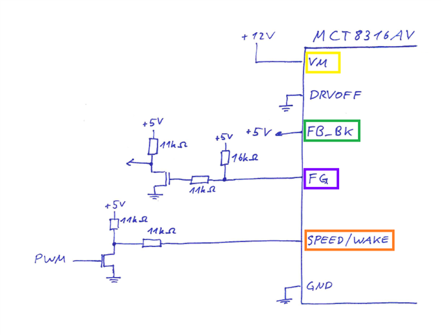
I configured a MCT8316A as PWM SetSpeed input.
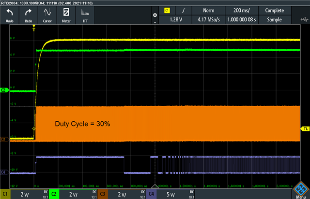
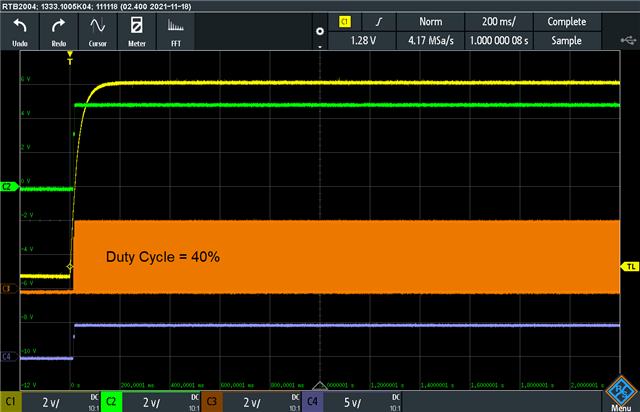
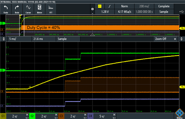
a) If a PWM signal is at the Speed Pin (e.g. 5kHz, Duty Cycle = 40%) during powering on hte IC with 12V --> The IC will stay in SYSTEM_IDLE (instead MOTOR_IDLE) and some fields have strange values* (see screenshot). The motor will not start up, also not, if enabling the 'Speed Control via I2C".
b) If I the PWM singal is 0% or 100% and then I power up the IC with 12V --> everything works fine (see red added values in the screenshot), and the motor starts up and varies according duty cycle.

Is there a configuration flag that can be set, to avoid the state a) ?

* VOLT_MAG = 0V, but DC_BUS_CURR = 83A   -->  ???


Thank you for your help

  • Additional information: If I start in a) and after some time, I set duty cycle to 0% then the IC goes immediately into state b)

  • Hi Emmanuel,

    Please check DRVOFF pin status, keep it low while powering up and test again.

    DRVOFF if high during powerup, some sections will be low power state.

    Thanks and Best regards

    Venkatadri S

  • Hi Venkatadri 

    Thank you for your input. The pin was floating so far. Now, I connected it to GND with a 10kOhm resistor. --> Result: If the applied duty cycle is below 25% (during power on) then the blower will start. If over 30% then I have still the case a) mentioned above.

    Additional question: If the the pins BRAKE or DIR are not used then the datasheet mentions a 10kOhm resistor to GND. In my case, I don't need DRVOFF, EXT_CLK, EXT_WD but the datasheet does not mention if to leave it floatend, or a resistor to GND, or hard wired to GND.

    Thank you and best regards
    Emanuel

  • Hi Emanuel,

    For case a) please probe DRVOFF pin, tie it to ground directly no need of 10k.

    EXT_CLK, EXT_WD can be left floating if disabled and DRVOFF need to be grounded.

    Thanks and Best regards

    Venkatadri S

  • Hi Venkatadri 
    Thank you for the information for the not documented pins, this will help for the next prototype.
    Now, I hardwired DRVOFF directly to GND. Result: No improvment.
    Please find attached pictures: Schematic and screenshots during power on with duty cycle 30% and 40% (sorry, the probes were not calibrated well). Maybe this pictures will help you.
    Brest regards, Emanuel

    Duty Cycle = 30%

    Duty Cycle = 30% (Zoom)

    Duty Cycle = 40%

    Duty Cycle = 40% (Zoom)

  • Hi Emanuel,

    Thanks for sharing good details. 

    I will verify and get back to you. 

    Thanks and Best Regards 

    Venkatadri S 

  • Any news or a work around?

  • Hi Emanuel,

    Thanks for reminding, I looked at the details but not able to find the reason.

    We need some more probing to root cause, 

    Can we test with following condition

    1. By reconfiguring FB_BK level to BUCK 3.3V in the EEPROM? For 5V, VM has to be stable above 6V and racing under high demand start can cause some disturbance.

    2. Capture same waveform for 25%, we will compare how VM is compared with higher duty. The high duty start can be loading VM source.

    Make sure hardwire of DRV is proper and no floating or pick up issues.

    Can you share full schematic and JSON file?

    Thanks and Best Regards 

    Venkatadri S 

  • Hi Venkatadri


    I use the MCT8316A-Eval-Kit for configurating our prototypes. Unfortunately, the I2C-pin of the expensive Eval-Kit got once more defective (always at 1.1V). Thus I have to buy a new one first :-( A more robust configurator/programmer that works with your GUI would be nice. I have to buy again a new expensive Eval-kit. But probably I will develop an Interface-PCBA first with a I2C-Repeater to limit the devolopment costs by not replaicing the Eval-Kait from time to time.

    1. 3.3V for FB_BK is not an option for the final product. As one can see from the screenshots, VM is not "digital" but rises continously as an usual supply voltage when switched on. It has no "fall-back" under 6V during switching on. If there is a configurable delay (betwen power on and using the PWM SetSpeed), that would be aceptable.
    2. I have to wait for a more robust programming/configuration solution. At the moment I have no device for programming/configuring a MCT8316A.

    Unfortunately, I cannot provide full shematic (that's why I draw the relevant schematic by hands, the MOSFETs are 2N7002*), but the voltage signals at the pins are shown in the screenshots. The 5V is generated with a 22uH inductor. The 5V doesn't drive other loads than shown in the hand drawn schematic).

    JSON file below as code (since there is no way for attaching such a file here)

    Best regards
    Emanuel


    * this is the reason, why we have to use 5V and not 3.3V

    {
      "signature": "oneui-register-data",
      "data": [
        [
          {
            "idx": 0,
            "id": "isd_config",
            "value": "0x7F444D00"
          },
          {
            "idx": 1,
            "id": "motor_startup1",
            "value": "0x06E55954"
          },
          {
            "idx": 2,
            "id": "motor_startup2",
            "value": "0x1BA4F9C4"
          },
          {
            "idx": 3,
            "id": "closed_loop1",
            "value": "0x1046A200"
          },
          {
            "idx": 4,
            "id": "closed_loop2",
            "value": "0x02A0CCF0"
          },
          {
            "idx": 5,
            "id": "closed_loop3",
            "value": "0x4CC40491"
          },
          {
            "idx": 6,
            "id": "closed_loop4",
            "value": "0x000CE944"
          },
          {
            "idx": 7,
            "id": "const_speed",
            "value": "0x00A00504"
          },
          {
            "idx": 8,
            "id": "const_pwr",
            "value": "0x09F04C84"
          },
          {
            "idx": 9,
            "id": "150_deg_two_ph_profile",
            "value": "0x36DB6DA6"
          },
          {
            "idx": 10,
            "id": "150_deg_three_ph_profile",
            "value": "0x36DB6D80"
          },
          {
            "idx": 11,
            "id": "trap_config1",
            "value": "0x054BA106"
          },
          {
            "idx": 12,
            "id": "trap_config2",
            "value": "0x2A880000"
          }
        ],
        [
          {
            "idx": 0,
            "id": "fault_config1",
            "value": "0x78F43025"
          },
          {
            "idx": 1,
            "id": "fault_config2",
            "value": "0x71466409"
          }
        ],
        [
          {
            "idx": 0,
            "id": "gd_config1",
            "value": "0x1C440002"
          },
          {
            "idx": 1,
            "id": "gd_config2",
            "value": "0x16A00000"
          }
        ],
        [
          {
            "idx": 0,
            "id": "pin_config1",
            "value": "0x2D720652"
          },
          {
            "idx": 1,
            "id": "pin_config2",
            "value": "0x000C0000"
          },
          {
            "idx": 2,
            "id": "device_config",
            "value": "0x7FFF0000"
          },
          {
            "idx": 3,
            "id": "peri_config",
            "value": "0x00000000"
          }
        ],
        [
          {
            "idx": 0,
            "id": "ana_trim3",
            "value": "0x48004800"
          },
          {
            "idx": 1,
            "id": "ana_trim4",
            "value": "0x00000000"
          },
          {
            "idx": 2,
            "id": "ana_trim5",
            "value": "0x0000000C"
          },
          {
            "idx": 3,
            "id": "ana_trim6",
            "value": "0x00000000"
          },
          {
            "idx": 4,
            "id": "ana_trim7",
            "value": "0x00000000"
          },
          {
            "idx": 5,
            "id": "ana_trim8",
            "value": "0x00004E73"
          },
          {
            "idx": 6,
            "id": "ana_trim9",
            "value": "0x007DB8A3"
          },
          {
            "idx": 7,
            "id": "ana_trim10",
            "value": "0x536E013B"
          }
        ],
        [
          {
            "idx": 0,
            "id": "algo_reserved1",
            "value": "0x00000000"
          },
          {
            "idx": 1,
            "id": "algo_reserved2",
            "value": "0x00000000"
          },
          {
            "idx": 2,
            "id": "algo_reserved3",
            "value": "0x00000000"
          }
        ],
        [
          {
            "idx": 0,
            "id": "gate_driver_fault_status",
            "value": "0x00000000"
          },
          {
            "idx": 1,
            "id": "controller_fault_status",
            "value": "0x00000000"
          }
        ],
        [
          {
            "idx": 0,
            "id": "sys_status1",
            "value": "0x007733C8"
          },
          {
            "idx": 1,
            "id": "sys_status2",
            "value": "0x200104B9"
          },
          {
            "idx": 2,
            "id": "sys_status3",
            "value": "0x0014003D"
          }
        ],
        [
          {
            "idx": 0,
            "id": "device_ctrl",
            "value": "0x00000000"
          }
        ],
        [
          {
            "idx": 0,
            "id": "algo_ctrl1",
            "value": "0x00000000"
          }
        ]
      ]
    }

  • Hi Emanuel,

    I wanted to verify MCT8316A section specifically, next we may need to see layout.

    Inductor part is proper but verify saturation current rating of inductor, recommended saturation of the inductor should be min 500mA.

    In order to isolate hardware issues, can we test with EVM?

    Thanks and Best Regards 

    Venkatadri S 

  • The internal buck converter is designed to be able to work without inductor but with a resistor too. Nevertheless, the used inductor has a saturation limit of 380mA which should be enough for the needed about 2mA output.
    All our EMVs are dead; so if you have an EMV at hand, you can test it - please let me know the result. (Note: It is not clear, who you mean with "we": Is it you (Texas instruments), or you (Venkatadri) and I (Emanuel)? Or do you mean just me (Emanuel)?)

    My current work arround is to specify, that the PWM duty cycle has to be 0% or 100% during power on (but not 1%-99%).

  • Hi Emanuel,

    I missed to respond to you before.

    Inductor saturation rating should be sufficient.

    What is causing I2C lines getting damaged, any possible electrical over stress? Pins abs max rating violation?

    Do you have MCT8316A samples? If available, please replace one with EVM and test same condition?

    Thanks and Best Regards 

    Venkatadri S 

  • Hello Venkatadri 
    As I wrote, I have to get a new EMV first. then I will add an I2C-isolator between the EMV and our prototype PCBA. Not the I2C-pins of the MCT8316A are going defective, but the I2C-pins of the microcontroller(!) on the expensive EMV. Thus I cannot configure our prototype PCBAs.
    I have urgent other projects so I cannot spend a lot of time for this MCT8316A issue at the moment. The MCT8316A (and MCT8329A) are for future long-terme products (replacing existing driver ICs), thus no hurry.
    Best regards, Emanuel

  • Hi Emanuel,

    Thanks for providing the details.

    We need to verify DRVOFF pin condition during power up, required to be stable low during power up.

    Hence, I wanted to verify with following methods to root cause

    1. Use the MCT8316A samples which are showing the issue, assemble it to EVM and test for same conditions - This clarifies if any noise on the custom PCB

    2. Probe DRVOFF pin, FG and nFault pin along with VM ramp.

    Thanks and Best Regards 

    Venkatadri S 

  • Hello Venkatadri 

    I got a new EMV and did no hardware change at all. Same issue: 12V supply voltage, same JSON file as shown above. Motor is not starting when a duty cycle of 1.5 - 98.5% prior applied than power supply voltage. If duty cycle is < 1.5% or >98.5% prior applied than power suppy voltage turned on, then the motor is starting accordingly.

    > We need to verify DRVOFF pin
    Do you want me to send you a picture of our hardwired DRVOFF pin to GND at our prototype PCBA?

    Regarding 1): Since the official bought EMV shows the same issue there is no need to desolder the MCT8316A out of the EMV and it replace with a MCT8316A out of our prototype PCBA. (I wouldn't desolder the MCT8316A out of the EMV anyway).

    Regarding 2): FG and VM can be seen in the oscilloscope screenshots above. DRVOFF is hardwired to GND (nothing to measure). nFault is not shown above but I have no time at the moment for that. And since nFault is an output indicator and not a "stearing value", I cannot influence the issue anyway. Since the issue can be reproduced with the official EMV you are able to measure all the signals you want at your EMV.

    Since the official EMV shows the same issue, we can close this issue as a bug in the IC?

    Best regards
    Emanuel

  • Hi Emanuel,

    The problem statement is, if there is duty command before powering up the device then problem occurs and same works if duty is applied after power up? Please clarify this.

    When motor not starting what is the system status? Is it SYSTEM_IDLE or any other fault?

    Also, any change to EEPROM can you program to EEPROM, power cycle and then test?

    I will plan to verify this condition by early next week and get back.

    Thanks and Best Regards 

    Venkatadri S 

  • Hello Venkatadri 

    The problem statement is, if there is duty command before powering up the device then problem occurs and same works if duty is applied after power up? Please clarify this.

    See first initial posting.

    When motor not starting what is the system status? Is it SYSTEM_IDLE or any other fault?

    See text and screenshot of the first inital posting.

    Also, any change to EEPROM can you program to EEPROM, power cycle and then test?

    What? Of curse, the EEPROM can be programed. I don't understand the process flow you want.

    I will plan to verify this condition by early next week and get back.

    Yes, please. If you test it at your lab, you can get all data that you want.

    Best regards
    Emanuel

  • Hi Emanuel,

    I am clear about the issue, we will verify.

    Thanks and Best Regards 

    Venkatadri S 

  • Hi Emanuel,

    We verified this condition and reproduced the behavior.

    Short term work around is boot with duty less than 1.5% and then increase the duty.

    We will update the data sheet.

    Thanks for allowing ups time to review this and we will update the details in the data sheet.

    I hope the work around will be simple for your system.

    Thanks and Best Regards 

    Venkatadri S 

  • Hi Venkatadri 
    Nice to read after all support evidences, that it's not my fault but a bug in the IC. So this topic can be closed.
    Thank you, Emanuel