DRV8353RS-EVM: DRV8353RS-EVM: Motor not rotating with the GUI tool

Part Number: DRV8353RS-EVM
Other Parts Discussed in Thread: DRV8353

Tool/software:

Hi,

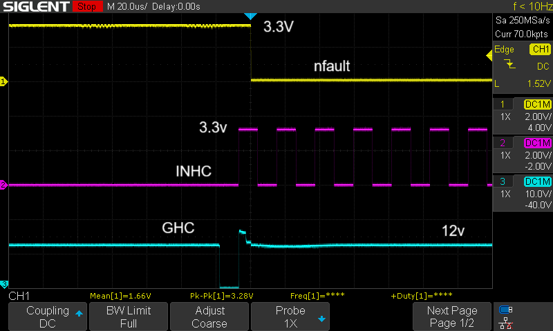
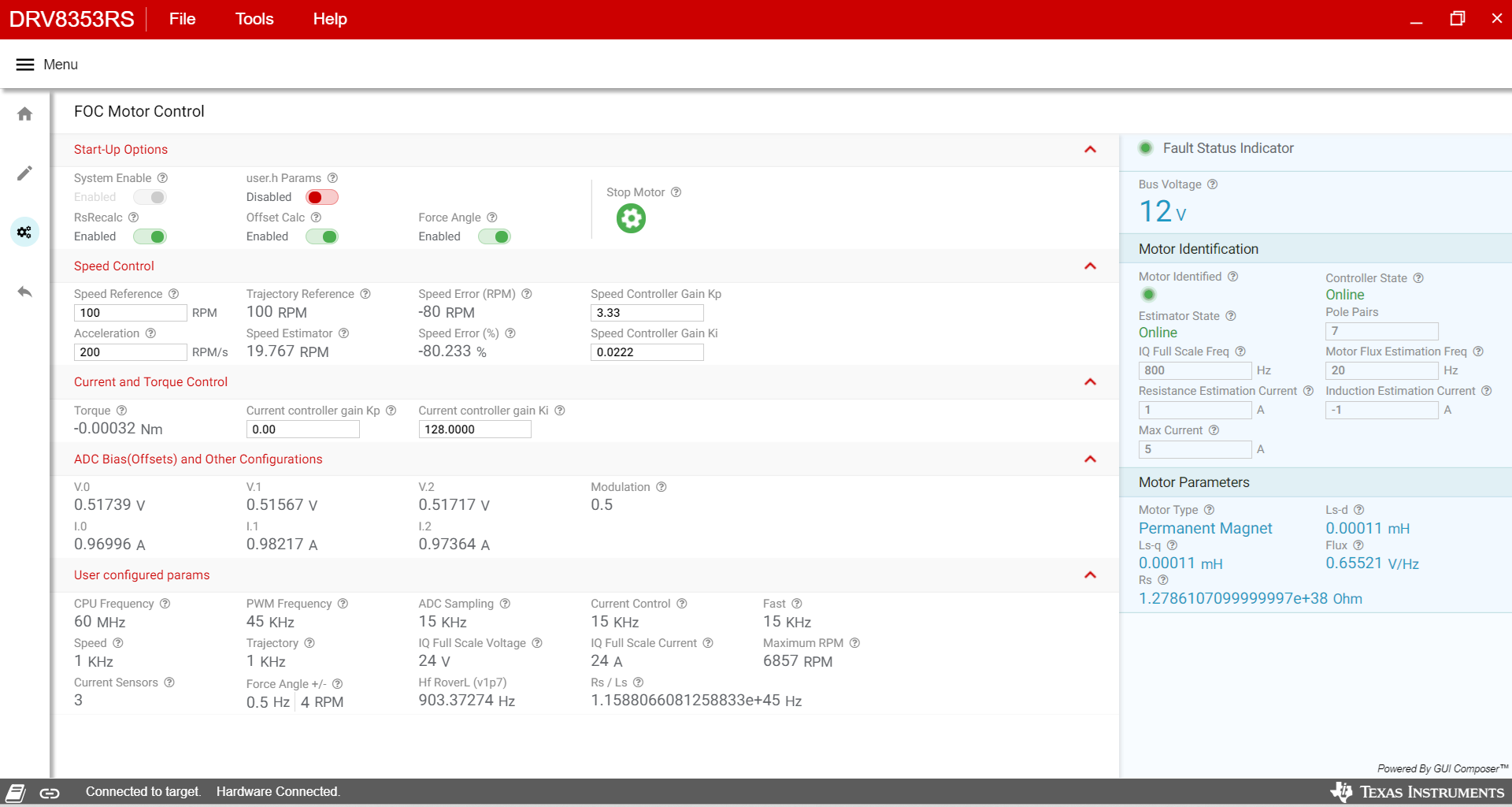
We are facing similar issue where the motor gets identified but not spinning, We tried two different motors, Both did not work.

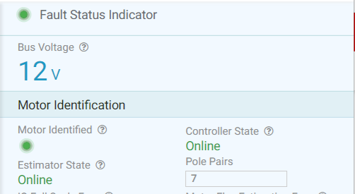
The attached screenshot is of 920KV Brushless DC Motor. Motor has 14 magnets, so we have entered 7 poles.
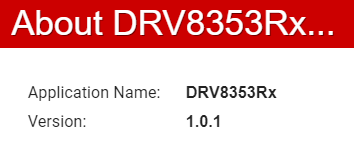
  

Software version:

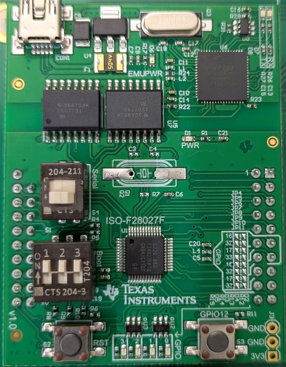
switch settings at default:


To check if EVM is working we disconnected the BLDC and started the process ,observed motor identification was green and  motor control /estimator state was also green. Not sure how motor was identified even after BLDC was disconnected.

Please advice how to troubleshoot this problem.

  • Hello,

    The motor identification process should still be able to run even without the motor connected. It will just populate with incorrect parameters. 

    As for the motor not spinning, I may need some more information. 

    1. Does the motor vibrate/move at all when attempting to spin? Or is there no movement at all

    2. Have you changed any of the register settings for the device?

    3. Does the device fault when attempting to spin?

    Thanks,

    Joseph

  • Hi Joseph,

    1) there no movement at all

    2) register settings have not be touched

    3) Yes, device fault red led turns on while attempting to spin.

  • Hello,

    Thank you for the extra information. This will help to find the root of the issue.

    Are you able to tell me which faults occur during startup?

    Here is something you should try:

    1. Before spinning, lower the IDRIVEP_HS, IDRIVEN_HS, IDRIVEP_LS, and IDRIVEN_LS in registers 0x03, and 0x04 from 0x1111b to something like 0x0001b. Too high of an idrive value may be causing your faults on startup.

    2. Make sure power supply can provide enough current and is not hitting its limit during operation.

    Thank you,

    Joseph

  • Hi,

    In GUI there are no errors, But red fault led gets on EVM.

    1) As per your instructions we tried to change and update registers but values are not updating.

    2) We have set voltage to 12v and 5 amp so there is more than enough power to make the BLDC spin.

  • Hello,

    Thank you for the extra information.

    I understand that the power is not a concern. But to me it looks like the registers update when you change. 

    I think we need to discover what is causing the board's fault LED to be on.

    Does the fault LED come on immediately when powering the board, and never goes away? Or will the LED come on only after attempting to spin the motor.

    Thank you,

    Joseph

  • Hello,

    If you carefully watch the video, I changed the values and click write registry, write complete notification pops but the values don't get saved, they return to their default.

    fault led comes on after attempting to spin the motor not after powering the EVM and stays on until power is restarted.

  • Hi Renu,

    I see. I forgot that this EVM only operates at those IDRIVE values. This is OK, I just wanted to make sure these settings were not at 1A/2A setting.

    It looks like the VDS_LVL setting should also be high enough to not trigger during operation.

    When you encounter the fault, do any of the values in registers 0x00 or 0x01 change? I know the GUI light does not change, but do any of the fault register values update?

    The other thing we can check now is the waveforms during operation to get clues about the issue.

    Can you probe INHx, GHx, SHx and nFAULT on the scope and trigger on falling edge of nFAULT? 

    Thank you,

    Joseph

  • Hi Joseph,

    No registers 0x00 or 0x01 do not change


  • Hi Renu,

    Just making sure you click read all registers button after fault occurs. You have auto-read setting off, so the registers will only update if you change that setting or if you hit the read all button.

    If you have done this and the registers still do not show anything we can continue debugging.

    Thanks,

    Joseph

  • Hi, Joseph

    I made a shield with STM32f103 (blue pill) for testing purpose .

    pinouts :

    INHA  PA8
    INHB  PA9
    INHC  PA10

    INLA  PB6
    INLB  PB7
    INLC  PB8


    SDI  PA7
    SDO  PA6
    SCS  PA4
    SCK  PA5

    ISENA  PA0
    ISENB  PA1
    ISENC  PA2

    NFAULT  PB5
    ENABLE  PB9

    rxPin  PB10
    txPin  PB11

    I am sharing test results below.

    1) SPI test (no motor connected):

    #include <SPI.h>
    #include <SoftwareSerial.h>

    #define rxPin PB10
    #define txPin PB11
    SoftwareSerial mySerial(rxPin, txPin);

    #define PIN_CS     PA4
    #define PIN_ENABLE PB9
    #define PIN_NFAULT PB5

    SPISettings drvSPI(500000, MSBFIRST, SPI_MODE1);

    uint16_t drvRead(uint8_t reg) {
      uint16_t cmd = (1 << 15) | ((reg & 0x7F) << 11);
      SPI.beginTransaction(drvSPI);
      digitalWrite(PIN_CS, LOW);
      delayMicroseconds(2);
      uint16_t resp = SPI.transfer16(cmd);
      digitalWrite(PIN_CS, HIGH);
      SPI.endTransaction();
      return resp & 0x07FF;
    }

    void drvWrite(uint8_t reg, uint16_t data) {
      uint16_t cmd = ((reg & 0x7F) << 11) | (data & 0x07FF);
      SPI.beginTransaction(drvSPI);
      digitalWrite(PIN_CS, LOW);
      delayMicroseconds(2);
      SPI.transfer16(cmd);
      digitalWrite(PIN_CS, HIGH);
      SPI.endTransaction();
    }

    void setup() {
      mySerial.begin(9600);
      delay(200);

      pinMode(PIN_CS, OUTPUT); digitalWrite(PIN_CS, HIGH);
      pinMode(PIN_ENABLE, OUTPUT); digitalWrite(PIN_ENABLE, HIGH);
      pinMode(PIN_NFAULT, INPUT_PULLUP);

      SPI.begin();

      delay(2); // Wait after enable

      if (digitalRead(PIN_NFAULT) == LOW) {
        mySerial.println("Fault active before SPI test!");
      }

      mySerial.println("Write/read test on reg 0x03 (Gate Drive HS)");

      uint8_t reg = 0x03;
      uint16_t orig = drvRead(reg);
      mySerial.print("Reg 0x03 before: 0x"); mySerial.println(orig, HEX);

      uint16_t test = (orig & 0x07C0) | ((orig ^ 0x001) & 0x003F);
      drvWrite(reg, test);
      delay(10);
      uint16_t after = drvRead(reg);
      mySerial.print("Reg 0x03 after write: 0x"); mySerial.println(after, HEX);

      drvWrite(reg, orig);
      delay(10);
      uint16_t restored = drvRead(reg);
      mySerial.print("Reg 0x03 restored: 0x"); mySerial.println(restored, HEX);

      mySerial.println("Done. Paste the three hex lines here.");
    }

    void loop() { delay(1000); }


    Result:
    Write/read test on reg 0x03 (Gate Drive HS)
    Reg 0x03 before: 0x3FF
    Reg 0x03 after write: 0x3FE
    Reg 0x03 restored: 0x3FF


    this shows SPI communication is good.


    2) PWM test (no motor connected):

    //pwm test
    #include <SoftwareSerial.h>

    #define INH_A PA8
    #define INH_B PA9  
    #define INH_C PA10
    #define ENABLE_PIN PB9
    #define FAULT_PIN PB5

    #define rxPin PB10
    #define txPin PB11
    SoftwareSerial debugSerial(rxPin, txPin);

    void setup() {
      debugSerial.begin(9600);
      delay(1000);
     
      debugSerial.println("\n=== NO MOTOR TEST ===");
     
      pinMode(INH_A, OUTPUT);
      pinMode(INH_B, OUTPUT);
      pinMode(INH_C, OUTPUT);
      pinMode(ENABLE_PIN, OUTPUT);
      pinMode(FAULT_PIN, INPUT_PULLUP);
     
      digitalWrite(INH_A, LOW);
      digitalWrite(INH_B, LOW);
      digitalWrite(INH_C, LOW);
      digitalWrite(ENABLE_PIN, LOW);
      delay(100);
     
      digitalWrite(ENABLE_PIN, HIGH);
      delay(200);
     
      debugSerial.print("nFAULT pin: ");
      debugSerial.println(digitalRead(FAULT_PIN) ? "OK" : "FAULT");
     
      if (digitalRead(FAULT_PIN)) {
        debugSerial.println("White check mark EVM OK without motor");
        debugSerial.println("Press 't' to test PWM outputs");
      } else {
        debugSerial.println("X EVM has fault even without motor!");
        debugSerial.println("Check power supply and connections");
      }
    }

    void loop() {
      static bool lastFault = true;
      bool currentFault = digitalRead(FAULT_PIN);
     
      if (currentFault != lastFault) {
        debugSerial.print("Fault status changed: ");
        debugSerial.println(currentFault ? "CLEARED" : "FAULT ACTIVE");
        lastFault = currentFault;
      }
     
      if (debugSerial.available()) {
        char cmd = debugSerial.read();
        if (cmd == 't' && currentFault) {
          testPWMOutputs();
        }
      }
     
      delay(100);
    }

    void testPWMOutputs() {
      debugSerial.println("Testing PWM outputs (no motor connected):");
     
      analogWrite(INH_A, 50);
      delay(1000);
      debugSerial.println("Phase A PWM active");
     
      digitalWrite(INH_A, LOW);
      analogWrite(INH_B, 50);
      delay(1000);
      debugSerial.println("Phase B PWM active");
     
      digitalWrite(INH_B, LOW);
      analogWrite(INH_C, 50);
      delay(1000);
      debugSerial.println("Phase C PWM active");
     
      digitalWrite(INH_C, LOW);
      debugSerial.println("PWM test complete");
    }


    Result:

    nFAULT pin: OK
    
    White check mark EVM OK without motor
    Press 't' to test PWM outputs
    
    Testing PWM outputs (no motor connected):
    
    Phase A PWM active
    Phase B PWM active
    Phase C PWM active
    PWM test complete
    Fault status changed: FAULT ACTIVE

    here fault pin turns on.
  • Hello,

    Thank you for the detailed testing.

    I see that your SPI is visibly working and you are able to PWM on each phase. 

    When you say "here the fault pin turns on." You mean that you encounter a fault and the nFAULT pin is pulled low?

    If this is the case, can you read registers 0x00 and 0x01 to see which fault occurs?

    If there is no fault, are you able to spin the motor?

    Thank you,

    Joseph

  • Hi Joseph,


    I managed to get BLDC working with STM32G474CEU6 and DRV8353S on Arduino IDE. So far, I’ve managed to get it running partially, but it’s not operating smoothly. I believe the high-side and low-side source/sink settings need to be fine-tuned for optimal performance.

    void configureDRV8353() contains my current settings.


    Program:

    #include <SPI.h>
    #include <SimpleFOC.h>
    #include <SoftwareSerial.h>

    // Debug on SoftwareSerial
    SoftwareSerial debugSerial(PC14, PC15);

    // Custom SPI for DRV8353 on SPI1 pins
    SPIClass drv_spi(PA7, PA6, PA5);  // MOSI, MISO, SCK
    #define DRV_CS_PIN PA4
    #define ENABLE_PIN PA3
    #define LOW_SIDE_EN_PIN PB7  // Low side enable

    // SPI2 pins for AS5047P sensor
    #define SPI2_MOSI PB15
    #define SPI2_MISO PB14
    #define SPI2_SCK PB13
    #define AS5047P_CS PB11
    SPIClass spi2(SPI2_MOSI, SPI2_MISO, SPI2_SCK);

    // AS5047P sensor config
    MagneticSensorSPIConfig_s AS5047P_SPI = {
      .spi_mode = SPI_MODE1,
      .clock_speed = 10000000,  // 10 MHz
      .bit_resolution = 14,
      .angle_register = 0x3FFF,
      .data_start_bit = 13,
      .command_rw_bit = 14,
      .command_parity_bit = 15
    };
    MagneticSensorSPI sensor(AS5047P_SPI, AS5047P_CS);


    // Motor parameters
    BLDCMotor motor = BLDCMotor(7);  // Replace 8 with your motor pole pairs

    // DRV8353S pins based on your hardware
    #define INHA_PIN PA0
    #define INHB_PIN PA1
    #define INHC_PIN PA2
    #define ENABLE_PIN PA3

    // Instantiate 3PWM driver with your pins (INHA, INHB, INHC, ENABLE)
    BLDCDriver3PWM driver = BLDCDriver3PWM(INHA_PIN, INHB_PIN, INHC_PIN, ENABLE_PIN);

    // Target velocity variable
    float target_velocity = 0;

    // Helper SPI functions for DRV8353 as before
    void spiSelect() {
      digitalWrite(DRV_CS_PIN, LOW);
      delayMicroseconds(10);
      debugSerial.println("DRV CS LOW");
    }

    void spiDeselect() {
      digitalWrite(DRV_CS_PIN, HIGH);
      delayMicroseconds(10);
      debugSerial.println("DRV CS HIGH");
    }

    void writeRegister(uint8_t reg, uint16_t value) {
      uint16_t command = (reg << 11) | (value & 0x7FF);
      uint8_t buffer[2] = { uint8_t(command >> 8), uint8_t(command & 0xFF) };
      debugSerial.print("Writing reg ");
      debugSerial.print(reg);
      debugSerial.print(": 0x");
      debugSerial.println(value, HEX);

      spiSelect();
      drv_spi.transfer(buffer, 2);
      spiDeselect();
    }

    uint16_t readRegister(uint8_t reg) {
      uint16_t command = 0x8000 | (reg << 11);
      uint8_t buffer[2] = { uint8_t(command >> 8), uint8_t(command & 0xFF) };
      debugSerial.print("Reading reg ");
      debugSerial.println(reg);

      spiSelect();
      drv_spi.transfer(buffer, 2);
      spiDeselect();

      uint16_t result = (buffer[0] << 8) | buffer[1];
      debugSerial.print("Read 0x");
      debugSerial.println(result, HEX);
      return result & 0x7FF;
    }

    void configureDRV8353() {
      digitalWrite(ENABLE_PIN, HIGH);
      digitalWrite(LOW_SIDE_EN_PIN, HIGH);
      delay(50);

      writeRegister(2, 0x7A0);  //PWM mode, enables overcurrent protection (OCP), fault reporting, other critical control
      delay(10);
      readRegister(2);
      //writeRegister(3, 0x313);  //high-side MOSFET gate drivers source ~50 mA, sink ~100 mA
      writeRegister(3, 0x334); // HS source: 100mA (idx 3), HS sink: 150mA (idx 4)
      delay(10);
      readRegister(3);
      //writeRegister(4, 0x413);  //low-side MOSFET gate drivers source ~50 mA, sink ~100 mA
      writeRegister(4, 0x434); // LS source: 100mA (idx 3), LS sink: 150mA (idx 4), CBC enabled
      delay(10);
      readRegister(4);
      writeRegister(5, 0x15);  //OCP -overcurrent protection mode (e.g., latched fault), dead time, deglitch time, and VDS threshold levels for fault detection.
      delay(10);
      readRegister(5);
      writeRegister(6, 0x280);  //current sense amplifiers
      delay(10);
      readRegister(6);

      debugSerial.println("DRV8353 configured.");
    }

    void setup() {

      pinMode(DRV_CS_PIN, OUTPUT);
      pinMode(ENABLE_PIN, OUTPUT);
      pinMode(LOW_SIDE_EN_PIN, OUTPUT);
      pinMode(AS5047P_CS, OUTPUT);

      digitalWrite(DRV_CS_PIN, HIGH);
      digitalWrite(ENABLE_PIN, LOW);
      digitalWrite(LOW_SIDE_EN_PIN, LOW);
      digitalWrite(AS5047P_CS, HIGH);
      debugSerial.begin(9600);

      while (!debugSerial)
        ;

      drv_spi.begin();
      drv_spi.beginTransaction(SPISettings(10000000, MSBFIRST, SPI_MODE1));

      spi2.begin();

      debugSerial.println("Starting DRV8353 + AS5047P + SimpleFOC...");

      configureDRV8353();

      sensor.init(&spi2);

      debugSerial.println("AS5047P sensor initialized.");


      // Enable verbose debug output
      SimpleFOCDebug::enable(&debugSerial);

      // Set driver power supply voltage (adjust per your supply)
      driver.voltage_power_supply = 15;  // Example 24V supply; adjust as per your setup

      // Limit max voltage applied to driver (protection)
      driver.voltage_limit = 12;  // Adjust per motor max voltage rating

      // Initialize the driver
      if (!driver.init()) {
        debugSerial.println("Driver init failed!");
        while (1)
          ;  // Halt execution on failure
      }

      // Link motor and driver
      motor.linkDriver(&driver);
      motor.sensor = &sensor;

      // Safety voltage limit for motor
      motor.voltage_limit = 6;  // Safe starting voltage limit
      motor.current_limit = 1.0;

      // Use open-loop velocity control mode initially
      motor.controller = MotionControlType::velocity_openloop;
      //motor.controller = MotionControlType::velocity;

      // Initialize motor motor hardware
      if (!motor.init()) {
        debugSerial.println("Motor init failed!");
        while (1)
          ;  // Halt execution on failure
      }

      motor.initFOC();

      motor.enable();

      debugSerial.println("SimpleFOC motor initialized.");


      debugSerial.println("Motor ready! Set target velocity with command 'T <value>'");
      delay(1000);
    }

    void checkFaults() {
      uint16_t faultReg0 = readRegister(0);  // Status Register 0
      uint16_t faultReg1 = readRegister(1);  // Status Register 1

      debugSerial.print("Fault Status Reg0: 0x");
      debugSerial.print(faultReg0, HEX);
      debugSerial.print(" | Reg1: 0x");
      debugSerial.println(faultReg1, HEX);

      // Optionally decode specific fault bits here if desired
      // Example: Over Current Protection (OCP) bit in Reg0 is bit 0 (check datasheet)
      if (faultReg0 & 0x01) {
        debugSerial.println(">> Over Current Protection Fault!");
      }
      if (faultReg0 & 0x02) {
        debugSerial.println(">> VDS Fault!");
      }
      if (faultReg1 & 0x01) {
        debugSerial.println(">> Over Temperature Warning!");
      }

      if (faultReg0 & (1 << 7)) {
        debugSerial.println(">> Over Temperature Warning (OTW) active!");
      }
      // Add other bit checks as needed per datasheet
    }

    void loop() {

      sensor.update();
      float angle = sensor.getAngle();
      debugSerial.print("Encoder angle: ");
      debugSerial.println(angle, 5);


      motor.loopFOC();
      motor.move(1);

      // Run command parser to read mySerial inputs
      //command.run();
    }


  • Hi Renu,

    Its good to see you have the motor spinning. I'm not sure that the issue is with the driver settings here. 

    To me it looks like control needs to be optimized for smoother operation. It looks like you need to be sending the inputs faster. The motor speed is not limited by the turn on time of the MOSFET (which IDRIVE settings change), as that is on the scale of nano-seconds here. 

    It seems that you are using the simpleFOC library for control. I would try looking into that and seeing if you can optimize the control.

    Thanks,

    Joseph