Other Parts Discussed in Thread: TIDA-020026, ,
Tool/software:
I'm making a board with 5 x DRV8889AQPWPRQ1.
I'm referring to Design app note: TIDA-020026, www.ti.com/.../tidueq5.pdf
which has 2 x DRV8889-A1.
The protection technique to use VCP is explained in guide SLVA835A, "Protecting automotive motor-drive systems from reverse polarity conditions"
www.ti.com/.../slva835a.pdf
part 4.1. It uses DRV3204-Q1 as an example to show Rlimit calculation.
For that device (DRV3204-Q1), its datasheet has section Charge Pump which specifies I(VCP) that
can be used for Rlimit calculation - 12mA.
But for my stepper DRV8889A-Q1, I find no such I(VCP) specified anywhere. (Why?)
So how to calculate values for Q4, and R14 in TIDA-020026's Protection circuit? ( If I use numbers from DRV3204, seems I would be ok with 1k, not 10k ..?)
I then need to extrapolate this for x 5 DRV8889A-Q1, to utilize same Input Protection circuit.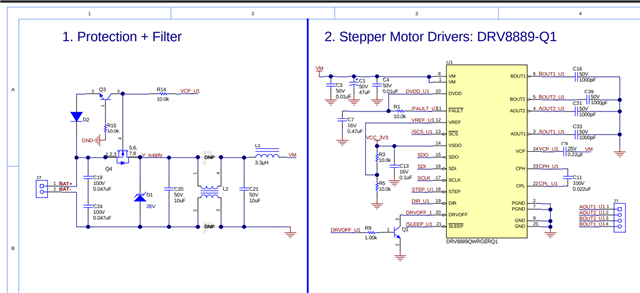
Help :)