Tool/software:
Hi,
*Not necessarily for "motor drivers forum" but this option is forced.*
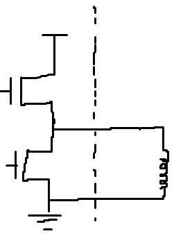
Question on your datasheet for the DRV8962DDVR. Section 7.4, it talks about fast decay and slow decay modes. It mentions in fast decay mode, the output is off and current recirculates through the body diodes and for slow decay mode, the low side FET is turned on and it actively shorts the output. Is the definition of these switched or is this correct? Wouldn't it be fastest to short the output.
Additionally, is my following understanding correct?
The chip can be used as an all on/off open/drain output (high side FET disabled), all on/off open/source output (low side FET disabled), or the PWM mode where the high and low side FET alternate turning on and off? Choosing one of these 3 modes is based on the In/En/etc. settings? Is this correct that it can operate in any of these modes?
Thanks,
Mark