Tool/software:
Hello TI Team
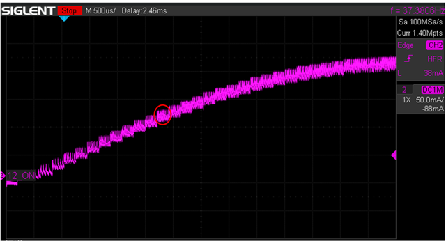
Set PPS: 200
Microstep: 32
Current: 200mA
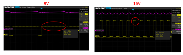
1. Testing the output terminal AOUUT+ and observing the output current, I found that the waveform shows individual bars at each step (as shown in the red box). What causes this phenomenon? How can I explain this phenomenon?
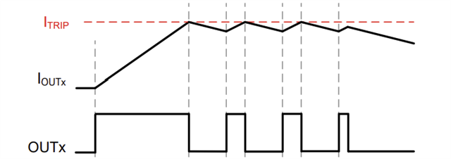
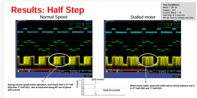
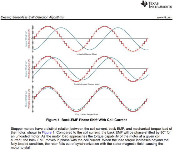
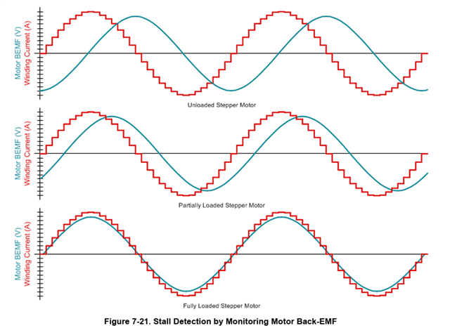
2. While the motor is running, I intentionally stalled it. Observing the output voltage and current, there are no abnormalities. How can I explain this?
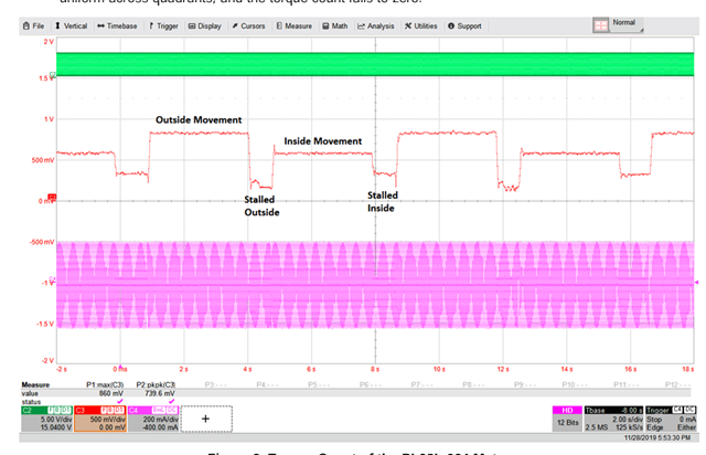
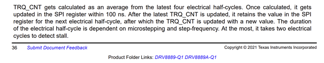
3. How can I detect when the motor stalls due to resistance during operation? Besides the stall detection method, are there any other parameters that can be used as indicators?