DRV8889-Q1: Stall Detection Methods

Part Number: DRV8889-Q1

Tool/software:

Hello E2E Experts,

Good day.

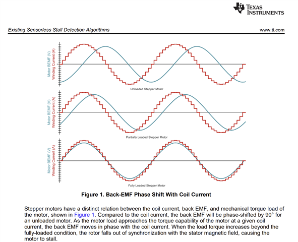
I’ve been reading the documentation Sensorless Stall Detection With the DRV8889-Q1, which explains the stall detection methods. In Section 3.2 (Constant OFF-time Method), it states that when the back-EMF increases, the T<sub>ON</sub> decreases, which results in more PWM cycles.

However, in Section 3.3 (PWM Cycle-Counting Method), it states that back-EMF decreases at stall condition, allowing a faster current rise time. This seems to contradict the explanation in Section 3.2.

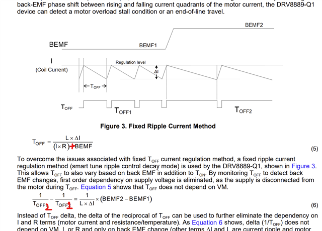
Additionally, in both Sections 3.2 and 4.1, the equations for Ton and Toff include the term (IR – BEMF). I’m unable to derive this term from the standard stepper motor equations, 

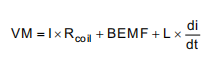
as the result i get is always (-IR-BEMF), and I’m wondering how it is obtained.

Regards,

TICSC

  • Hi,

    Thanks for your post. 

    Here's more specific information about the relationship between BEMF voltage and stepper motor current. Regardless of the current waveform the BEMF voltage will be a sinewave as the rotor spins through the field flux. As well as, the phase difference between the VBEMF and Icoil aka load angle proportionally represents the load torque at the motor mechanical output. With no to very light load, the load angle would be almost 90 ° and fully loaded and about to stall the load angle would be near 0 °. The stepper motor either spins synchronously or abruptly stalls, there is no in-between state. As long as the motor spins the VBEMF will be available, the load angle is what allows detection of the motor stall, or specifically an impending motor stall.  

    However, in Section 3.3 (PWM Cycle-Counting Method), it states that back-EMF decreases at stall condition, allowing a faster current rise time. This seems to contradict the explanation in Section 3.2.

    As described in the previous paragraph, the VBEMF will be 0 at stall - physical stop. With no BEMF factor, the tON will be much shorter time comparing to tON with the presence of VBEMF. However, it may not be a reliable parameter to detect stall detection. because it could also vary with the phase of the VBEMF. VBEMF could add or subtract voltage to the equation depending on its phase at a particular instant.

    TI does not use tON based or PWM cycle count based methods with our integrated stepper drivers with stall detection functionality. So we do not intend to dive into details of these methods.

    We use the approach described in section 4 DRV8889-Q1 Stall Detection Algorithm of the application note you referenced. Keep in mind these high level formulae are provided for a basic understanding of TI proprietary approach and by no means they represent the complete algorithm calculations which are TI internal information only. These are for the purpose of understanding the theory of operation of our algorithm at a high level. 

    I’m unable to derive this term from the standard stepper motor equations, 

    In real world with stepper motors, while VM is a DC parameter, components such as I x Rcoil, BEMF and L x di/dt are time variant parameters with in phase and out of phase components. To get the voltage magnitude (scalar) component across the coil of a spinning stepper, consider this equation VM or coil VTOTAL = √((I x R)² + (L x (dI/dt))²). Thank you. 

    Regards, Murugavel 

  • Hello Murugavel,

    Good day.

    What confuse me is that in the equation for toff it is (IxR)-BEMF instead of -((IxR)+BEMF). During toff, since VM = 0, the equation becomes
    0 = (I x R) + (L x (dI/dt)) + BEMF;
    dI/dt = -((I x R)+BEMF)/L
    for a short period of time, i assume that dt=toff, and dI = the current ripple(negative)
    which give me:
    toff = LxdI/((I x R)+BEMF)
    This results to toff increase when BEMF decrease, which is completely different from the result in section 4.
    Could you clarify whether I’m misunderstanding the derivation, or if there’s an additional assumption in the documentation that explains this difference?

    Regards,

    TICSC

  • Hi,

    Thanks for the follow up. Regarding the question about the specific equations we'll have to check with the author of this document and get back to you. This may take a few days. We'll get back to you early next week.

    Regards, Murugavel 

  • Hi,

    Thanks for your patience. We expect to get an answer within the next couple of days. 

    Regards, Murugavel 

  • Hi,

    What confuse me is that in the equation for toff it is (IxR)-BEMF instead of -((IxR)+BEMF).

    The term could be either (I x R) - BEMF or (I x R) + BEMF depending on the phase of the BEMF. TOFF may increase or decrease depending on this. 

    This results to toff increase when BEMF decrease, which is completely different from the result in section 4.

    Please keep in mind the diagram and the equation may or may not correlate. They are used for high level representation only. 

    Could you clarify whether I’m misunderstanding the derivation, or if there’s an additional assumption in the documentation that explains this difference?

    You are not misunderstanding the derivation part. The assumptions may be related to the phase difference between BEMF and current quadrants in the sine wave current. Further details are outside the scope of our public forum discussion as these are pertaining to the details of a TI proprietary algorithm.

    It is okay for you to go with the below as long as you keep the phase polarity in consideration depending on the time instants. Thank you.

    Regards, Murugavel