Tool/software:
Hi all,
we are planning to use the DRV8316 to drive a PMSM with a PWM frequency of 100kHz at 24V using the 3x PWM mode. Currently we are still using the DRV8316REVM evaluation board.
The problem is, that there is very noticeable distortion of the phase voltage around the zero crossing of the current. This in turn leads to distortion in the current which is detrimental to our motor controller.
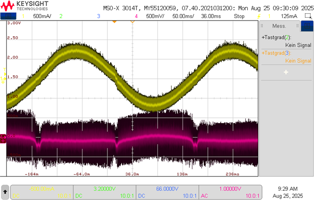
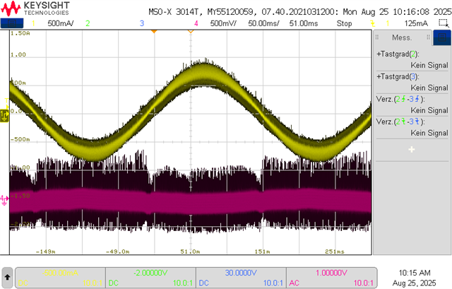
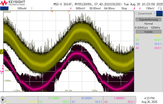
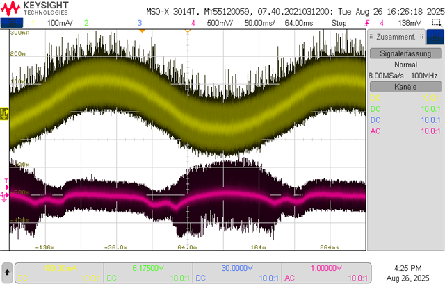
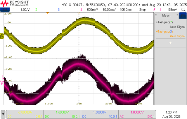
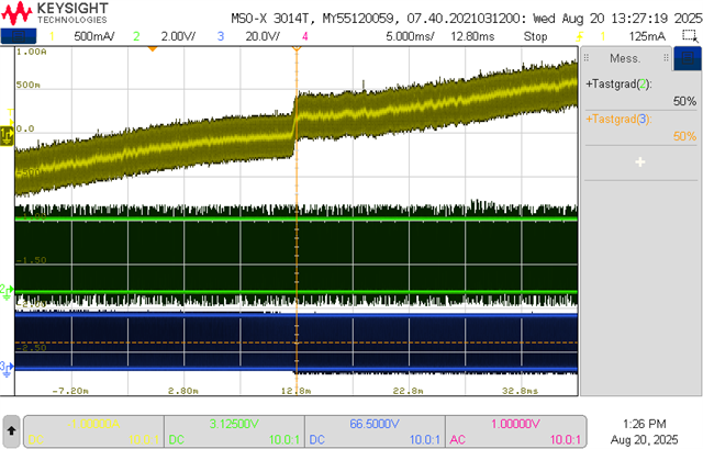
The following screenshot shows the current of phase A (CH1, flowing from driver to motor), and the corresponding low passed phase voltage at OUTA (CH4, through RC-lowpass and AC coupled) for an open loop sinus voltage:
The waveforms look similar to the "zero current clamping distortion" effect. It is my understanding, that the delay compensation feature of the DRV8316 is intended to remedy the distortion of the output duty cycle as mentioned in the last chapter of this application note https://www.ti.com/lit/an/slvaf84/slvaf84.pdf. However, we can measure that the output duty cycle at OUTA is smaller than the input duty cycle at INHA during the distortion.
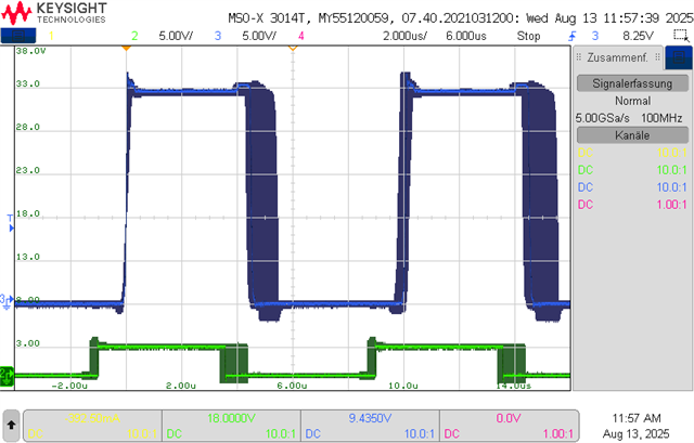
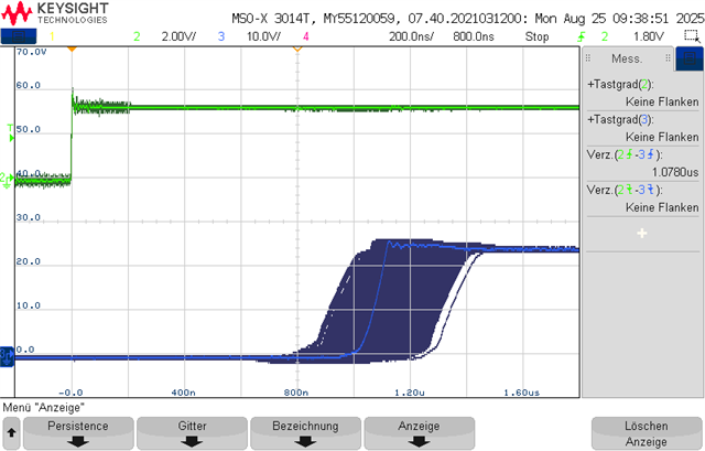
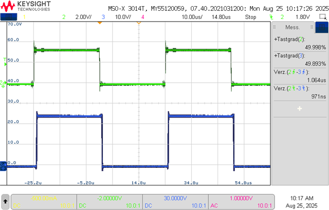
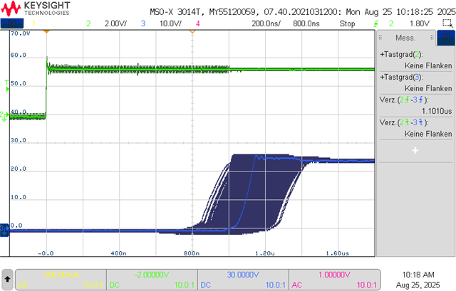
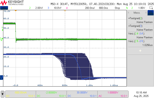
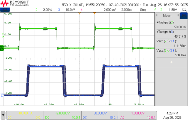
overview (CH1 current, CH2 INHA, CH3 OUTA):
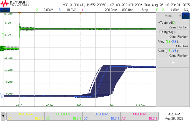
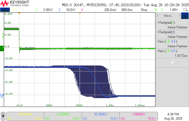
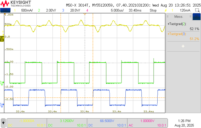
before distortion (duty cycle 0.9% decreased):

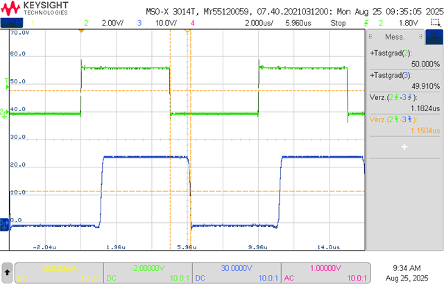
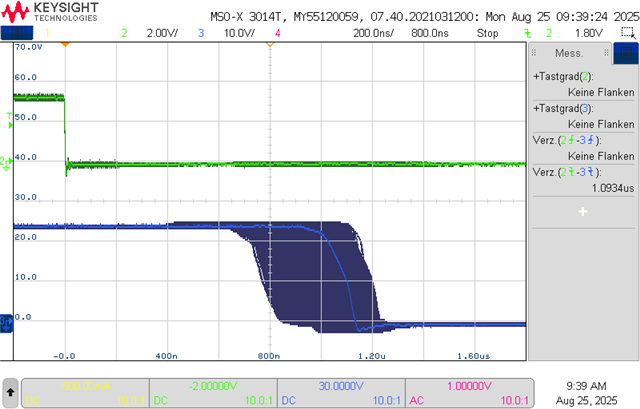
during distortion (duty cycle 2.3% decreased):
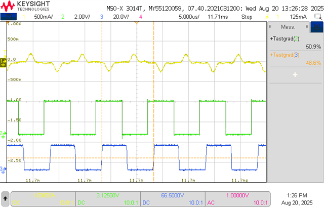
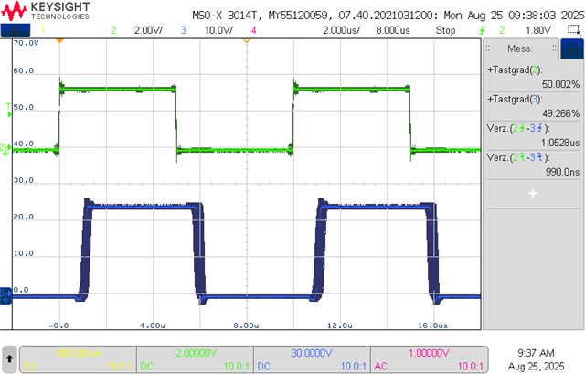
after distortion (duty cycle 0.9% decreased):
Related DRV8316 parameters:
- slew rate = 200V/us
- PWM mode = 3x mode
- driver delay compensation = enabled
- delay target = 1.2us
Motor parameters:
- phase to phase resistance: 1.27Ohm
- phase to phase inductance: 123uH
We conducted some more experiments:
- reducing PWM frequency: effect vanishes at around 20kHz
- increasing delay target: no improvement
- reducing delay target: more distortion until distortion of whole waveform
- reducing slew rate: not much of a difference, lowest setting distorts whole waveform
Do you have any experience with this effect, and is there a way to prevent the distortion? Do you agree that the delay compensation feature is intended to prevent the distortion?
I am looking forward to hearing from you.
Kind Regards, Dominik