DRV8424: The AOUT pin output have a drop

Part Number: DRV8424

Tool/software:

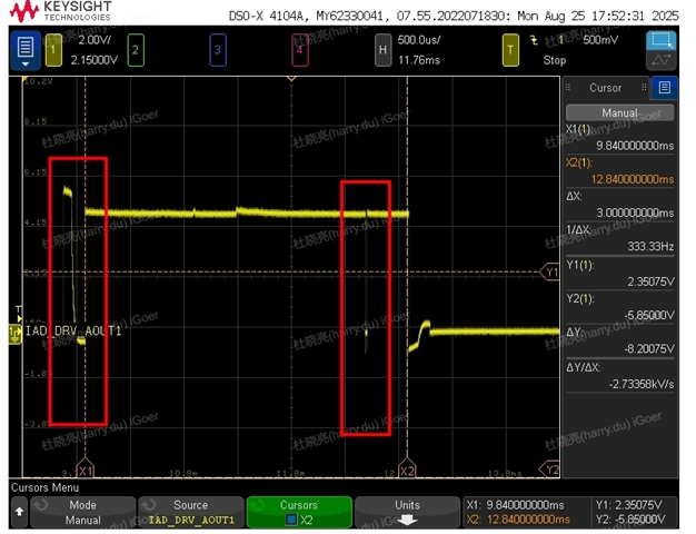
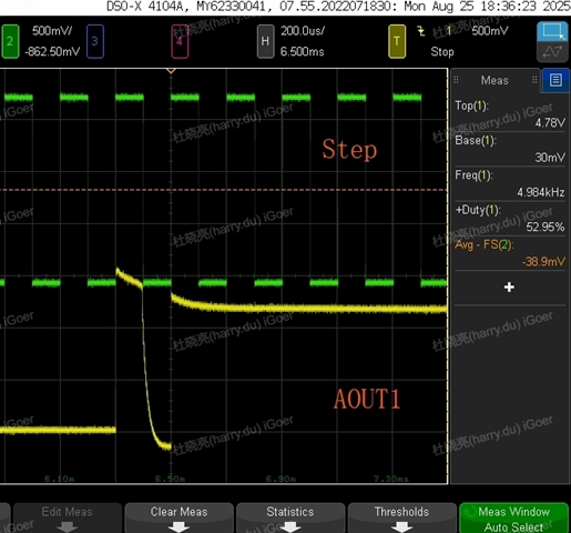
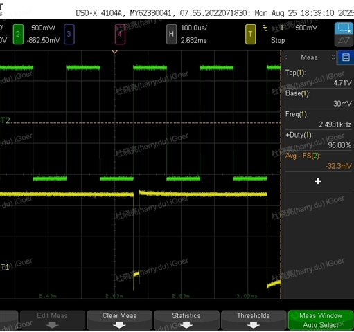
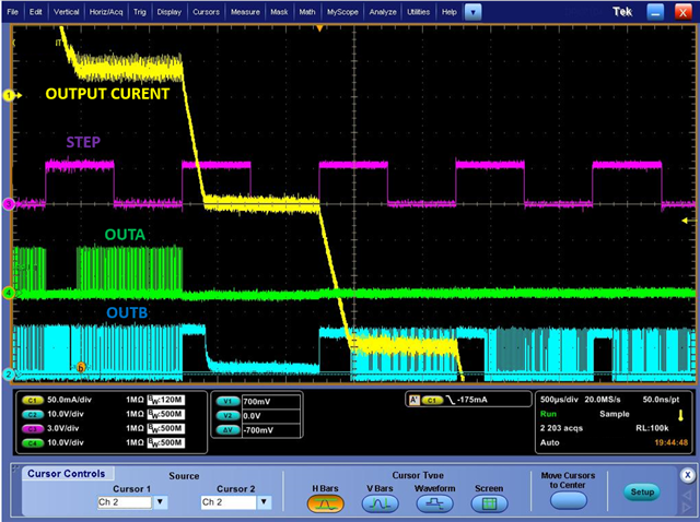
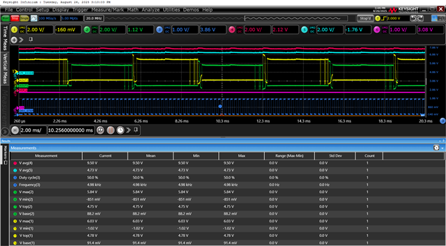
we set the step pin frequency is 5KHZ and the motor can rotate normally, but from the waveform of AOUT pin we found a "drop" and a abnormal pulse, colud ti team can help to confirm if it is correct?  

If it is abnormal, can you help to give us some advice for this. 

Thanks.

  • Hi Du, 

    Thank you for contacting us.

    To better assist you, I need a bit more information. The Aout1 output should alternate between low and high with each step pulse, adjusting based on the microstep and decay modes.

    Could you please share the schematic? Also, could you clarify the following:

    Microstepping mode: Which microstepping mode is currently configured?
    Decay mode: Which decay mode is currently selected?
    VREF: What is the current VREF voltage?
    Input voltage: What is the input voltage being used?

    could you please provide measurements for:  A output current, Step input signal, Aout1 output voltage, Aout2 output voltage

    The output voltage switching is designed to regulate the current, and with each step pulse, the current is adjusted based on VREF. The OUT outputs switch accordingly to maintain this regulation, as illustrated below. However, in provided captures by you, the output voltage is fixed for several step pulses which are not following the microstep modes. 

    Best regards, 

    Mojtaba

  • Hi Mojtaba

    Thanks for your reply.

    Microstepping mode: 1/8 (M0 =1, M1 = 1)
    Decay mode: DECAY_0 = 0; DECAY1 = 0;
    Vref:1.8V
    Input Voltage: 4.8V

  • Hi Du, 

    Thank you for providing the information.

    The 1/8 microstepping configuration divides each quadrant of the current into 8 steps, and the output voltage should switch accordingly to provide the corresponding step current. However, in the waveform you provided, the output voltage remains at a fixed high value, which implies that it is delivering 100% of the full-scale current (IFS). With VREF set to 1.8V, the IFS current is calculated to be 1.32A. If the motor current is low the motor current may not be regulated. Could you please measure the output current and also provide the motor's resistance and inductance values?

    Best regards, 

    Mojtaba

  • Hi Mojtaba

    Which motor's  resistance and inductance values do you want to know

    Another question, are the step frequency and OUTA frequency  the same?

  • Hi du, 

    Which motor's  resistance and inductance values do you want to know

    This question is unclear to me. The DRV8424 is stepper motor driver. Would you please explain what type of motor you control and what do you mean by which motor. The stepper motor winding resistance and inductance which can be found in motor datasheet.

    are you using the DRV8424EVM evaluation board, or did you design your own circuit board? If you designed your own board, please share the schematic to be reviewed by TI.

    Also, could you please measure the motor output current?

    Another question, are the step frequency and OUTA frequency  the same?

    No, the step frequency is different than output voltage frequency (switching frequency). The step frequency sets the desired motor speed using the following formulae. the step pulse is a PWM signal which is applied to step pin. 

    Please let me know if you have any questions. 

    Best regard, 

    Mojtaba.