DRV8874: Using as TEC controller, problems with PWM/Direction mode, brake function?

Part Number: DRV8874

Tool/software:

Hi, 

I'm implementing a TEC (Thermoelectric cooler) for a 24V, 3A TEC module. I use the DRV8874 with the following connection:

EN/IN1: PWM input

PH/EN2: Direction input for cooling or heating. 

PMODE = low, PH/EN input

IMODE 10kOhm to GND

Iprop = 1k

Vref = 1,4V for ca 3A Current limit.

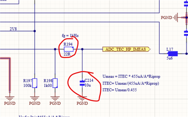
I connected in series to OUT1 and OUT2 a 5u6 (current rating 6A) choke, the filter caps I connected first to GND from the end of the choke and alos from TEC+ to TEC-

Connection to GND:

I connected also teh caps parallel to the TEC elemen:

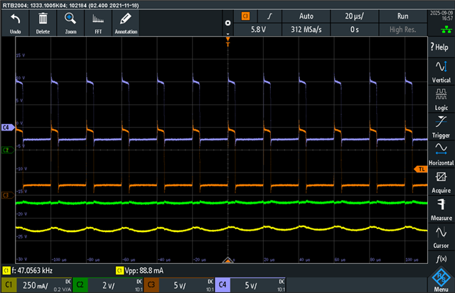
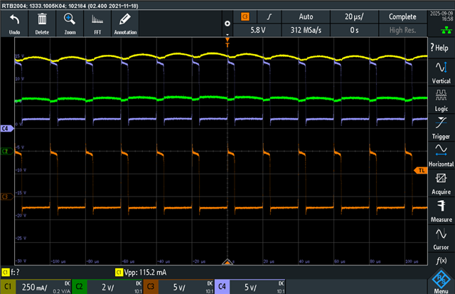
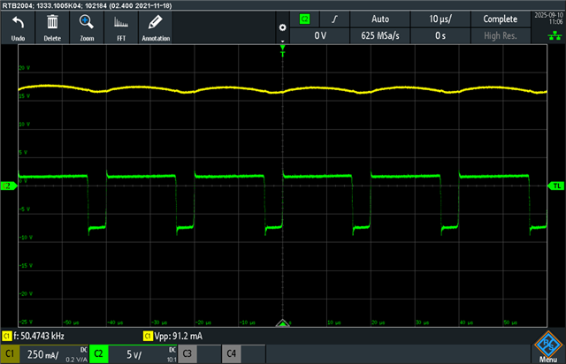
I work with a PWM frequency of 30kHz and a duty cycle of 20%, for testing. teh chokes are getting hot, and the behaviour is not as expected the current is increasing with increasing cuty cycle. 

But, with out load (TEC), the current is also flowing somewhere. 

Question, is the brake function of the DRV8874 working against me? Currently I have only one PWM output  available. 

Thanks

Philipp 

  • Hi Philipp,

    Thanks for your question.

    Question, is the brake function of the DRV8874 working against me? Currently I have only one PWM output  available. 

    This is known as brake function only when used to drive a BDC (brushed DC) motor. With general loads such as LC-filter and TEC this is slow decay and it is perfectly okay to use, in fact the suggested approach.

    IMODE 10kOhm to GND

    You mentioned IMODE was 10 KΩ to GND. But the schematic shows 0 Ω. Please check. The current regulation TOFF for this device is 25 μs. 30 kHz PWM period would be 33.33 μs. For 20 % duty cycle the on time would be 6.67 μs not enough time for a full TOFF if IMODE = GND. You could use the cycle-by-cycle mode but RIMODE must be either 20 kΩ or 62 kΩ to GND. In these modes the PWM frequency may have to be increased for proper current regulation - the point here is the off time must be shorted than the TOFF of 25 μs. See section 7.3.3.2.2 Cycle-By-Cycle Current Chopping in the datasheet.

    Lastly the RC filter on the IPROPI seems like a load because the charging current would be so low for such a high value capacitor. You may want to increase the R194 significantly and reduce C214 or insert an opamp buffer. The AIPROPI for this device is 450 μA/A. Loading on the IPROPI would impair current regulation operation, its response time. 

    Could you please share the load voltage and current waveforms? Thank you.

    Regards, Murugavel 

  • Hi Murugavel, 

    thanks for your fast response!

    I changed the IMOD resistor to 20k (to GND). the output filter is now R194 = 1k, C214=100nF. 

    I also changed the switching frequency to 80kHz. 

    Attached you can find two plots for the output filter configuration: Caps parallel to TEC, not to GND. As given in the second picture of the initial post

    Yellow: Current trough TEC

    Green: Voltage accross TEC

    Orange: TEC_N voltage wrt GND

    Violet: TEC_P_voltage wert GND

    DIR=0, fsw80kHz, DC=0,2

    DIR=1, fsw80kHz, DC=0,2

    The used inductors are 74439346056 from Würth with a nominal current of 8A. Nevertheless, at DC 0.4 they get a temperature of about 65°C. 

    Vref is reduced to 1,4V. 

    Should I change the output filter configuration back to the initial one with the caps connected to GND?

    Thanks a lot

    Philipp 

  • Hi, 

    I changed to cap configuration as given in the first picture, with all caps to GND. 

    The ripple current is doubled, and the temperature rises up to 70°C. 

    thanks

    philipp

  • Hi Philipp,

    Thanks for the follow up.

    The output of the DRV8874 or similar brushed motor driver full-bridge would be a PWM output aka square wave. The LC filter (second order) is used for cleaning up the ripple in the current. 

    I changed to cap configuration as given in the first picture, with all caps to GND.

    This is the commonly used configuration for filtering in a TEC driver. Either topology is fine, but the second picture connection doubles the effective capacitance of these capacitors across the TEC hence lower ripple by ~ 2x. 

    The scope captures look normal to me. 

    The used inductors are 74439346056 from Würth with a nominal current of 8A. Nevertheless, at DC 0.4 they get a temperature of about 65°C. 

    I looked at the saturation current specification. The 10 % inductance drop DC current is 5.8 A which has good margin for 0.4 A. Not sure why the inductor is getting hot. The typical DC resistance is 15 mΩ, I think the heat is unrelated to I2R loss. Purely a magnetics issue. Perhaps you may want to check with WE and find a suitable inductor different core material to minimize high frequency heating.  

    I changed the IMOD resistor to 20k (to GND). the output filter is now R194 = 1k, C214=100nF. 

    The IPROPI output filter should be better now from a loading the IPROPI output standpoint. Were you able to measure the voltage and ensure it matches with the calculated value for the output current? You could also do a scope capture and compare. Thank you.

    Regards, Murugavel  

  • Hi Murugavel, 

    thanks again for your fast response! I measured the votlage accross the inductor L15, see below (green curve). I used a differential probe connected to the scope. 

    When I use the 15mR of the inductor, the current with a drop of 10V (!) results in hundreds of Amps (660A) for the short time of 10us. 

    I see the same current even with no load connected to the LC output filter. 

    I measured the Imon port: (orange voltage at Imon)

    Something about 700mV. The DMM and current clamp give my a DC current value of 1A (ca).

    The computed current is higher: Itec = 0.7V(455uA/A*1k) = 1.5A

    There is still a missunderstanding from my side about the behaviour of the current trough the inductor. And the temperature corresponding temp. rise. 

    thanks

    philipp 

  • Hi Philipp,

    When I use the 15mR of the inductor, the current with a drop of 10V (!) results in hundreds of Amps (660A) for the short time of 10us. 

    The equivalent of an inductor would be an L and R in series, so 5.6 μH in series with 15 mΩ for the inductor in your system. The impedance of this L+R would be Z = √(R² + XL²), R is the DC resistance of the inductor and XL = 2πfL, f - frequency and L - inductance. Consider the Z of the inductor at the PWM frequency, not just the 15 mΩ for current calculation. The current through the inductor would be the sum of the current through the TEC + current through the capacitors, consider the AC behavior for the capacitor. 

    I measured the Imon port: (orange voltage at Imon)

    Something about 700mV. The DMM and current clamp give my a DC current value of 1A (ca).

    The computed current is higher: Itec = 0.7V(455uA/A*1k) = 1.5A

    This represents the total current via the LS-FET to GND of the conducting LS-FET. Increasing the value of the series inductance, for example to 22 μH and reducing the total capacitance to 22 μF or even 10 μF would increase the impedance of the inductor at the PWM frequency (80 kHz), keep the cutoff frequency in the same range and reduce the power lost in the filter and still keep the TEC current ripple to a reasonable value. Thank you.

    Regards, Murugavel