DRV8329-Q1: Power Management

Part Number: DRV8329-Q1
Other Parts Discussed in Thread: DRV8329

Tool/software:

Hello

We have designed TI IC That MCU and Gate Driver (MCU : F2800156 / Gate Driver : DRV8329-Q1)

But, There is problem so please check and give solution

1. Situation

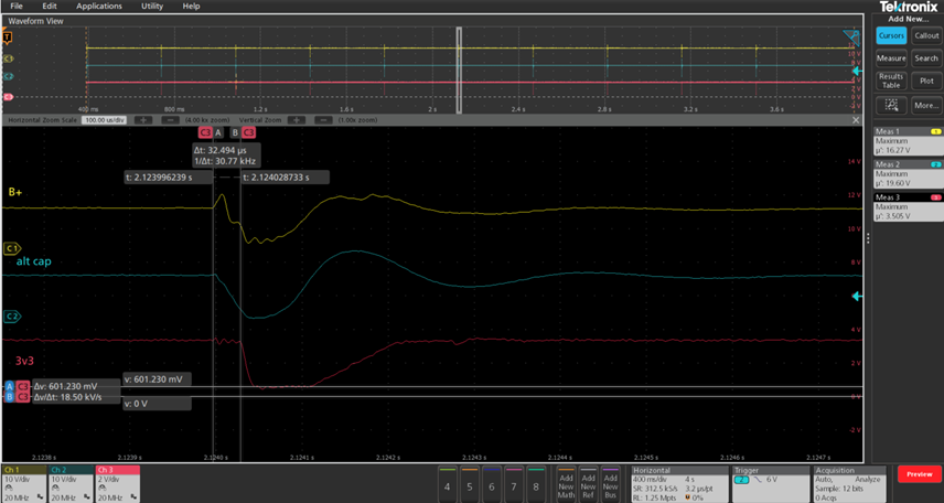
  • During the phase-to-GND short-circuit fault diagnostic test, the fault cannot be latched/confirmed.

  • Root cause: When the short occurs, the gate driver supply voltage drops momentarily, which causes the 3.3 V rail for the gate driver and MCU to sag.

  • As a result, the MCU (TI F2800156) resets and fault confirmation fails.

  • Gate Driver used: DRV8329-Q.

2. System Conditions

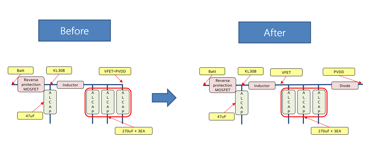
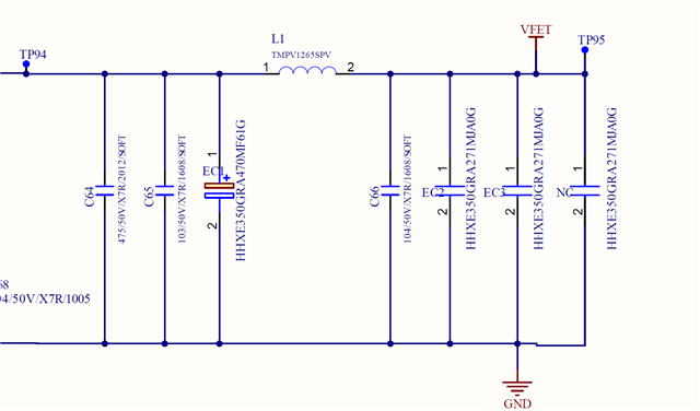
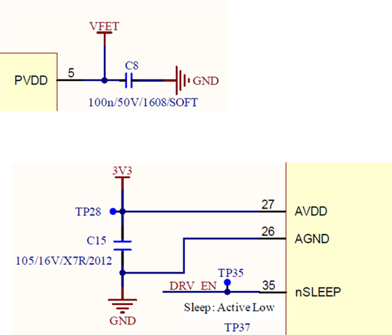
  • Please refer to the attached schematic.

3. Constraints

  • The MCU must sustain operation for the required hold-up time (refer to datasheet).

4. Attempted Solution

  • Added ~600 µF capacitor on the 3.3 V rail, but this is not a practical solution.

Request
Could TI suggest a practical solution to prevent the MCU from resetting under this condition?
Schematic and waveform data are attached for your review.

  • Input: 12 V

  • POW_SUP: Node after the battery → filter → reverse polarity protection FET

  • Hello,

    I understand that putting extra capacitance on the 3.3V rail is not practical. 

    But I do want to ask, do you have sufficient capacitance on the gate driver supply voltage? If you can increase capacitance here, then the supply sag will be less, and therefore 3.3V rail will also sag less.

    Please let me know if it is possible to add more capacitance onto DRIVER supply and see if it helps reduce sag on 3.3

    Thank you,

    Joseph

  • Hello Joseph

    Thank you for reply

    i think i have sufficient capacitance to gate driver supply voltage

    gate dirver supply voltage is PVDD, and same node VFET That is MOSFET Drain voltage

    We have 270uF * 3EA  + 47uF * 1EA Capacitor and  we consider VFET and PVDD Node seperate by using diode

    Could you give me your opinion Capacitance Value and Seperate node(VFET and PVDD)

    Have a good day

    Thank you

  • Hello,

    Thank you for the update. Would you be able to provide some more information so I can continue to debug?

    1. Can you provide schematic, including marked position of where you are probing, and also including the capacitor value and capacitors voltage rating

    2. Can you describe the Phase to GND short test you are performing? I am now thinking, how can VBAT be affected by Phase-to-GND short, if high side mosfets are off.

    Thank you,

    Joseph

  • Another option would be to lower the duration of the phase to gnd short test, so that the caps can support the transient. DRV device is not the issue here as there is no issue with the operation. The test is just shorting the Vbat causing the problem here.

  • Hello

    Thank you for your reply

    i answer your question

    1. i think i will share schematic, how to share you?

     - 47uF/35V *1EA   270uF/35V * 3EA

    2. The Phase-to-GND short test is a customer requirement.
    In case of a high-side to GND short, our application must stop operation; therefore, this fault diagnosis test is mandatory.

    Test condition: BAT, IGN = 12 V / During motor operation, Phase-to-GND short.

    • The fault is detected, but fault confirmation is not possible since the MCU resets and the fault counter is initialized.

    Currently, we are considering the option of changing the VDSLVL value.

    • Present setting: 3.3 V × 1k / (5.1k + 1k) = 0.541 V

    3.Additionally, I would like to hear your opinion on the approach of separating the VFET and PVDD nodes using a diode.

    Best Regard

  • Share PVDD and AVDD SCH

  • Hello,

    You should not need to change VDS_LVL value here, because the device already recognizes the fault during short condition. 

    The problem is that the your supply is dropping too low which causes the part to lose power and your 3.3V to turn off. This is not an issue with device recognizing the fault which is why you don't need to change VDS_LVL

    To fix this issue you must prevent VBAT from dropping.

    As for diode, it is usually not recommended to separate VDRAIN and PVDD with a diode. This is because it can sometimes prevent reflow to the supply which may cause large transients spikes in the system that can damage other parts.

    Thank you,

    Joseph

  • Hello

    Thank you for spending your time

    well, you dont recommend to use diode for seperate VDRAIN AND PVDD

    and How to solve this problem?? do you recommend any idea??

    Thank you

  • Hello,

    For the DRV8329 device, you do not need to split PVDD and VDrain.

    1. You should try to increase local capacitance on PVDD near device (C8). This may help to keep the device powered long enough to report fault and stay powered. 

    2. You can try to lower the VDS LVL in order to try to get the fault to detect earlier.

    The combination of 1 and 2 may help to solve your issue. Let me know if you can try this and it does not work.

    Thank you,

    Joseph