MCF8329A-Q1: (Current loop) control algorithm

Part Number: MCF8329A-Q1
Other Parts Discussed in Thread: MCF8329A

Tool/software:

Dear TI-experts,

we are currently working on your chip MCF8329A-Q1 with the EVM and I am trying to understand the control algorithm.

The first question is how does the auto calculation of the parameters work? What are the assumptions or goals of the closed loop, e.g. rise time/time constant? I would like to have the equations and explanations.

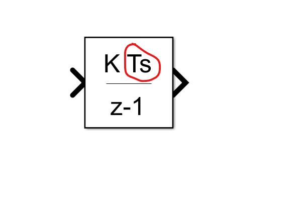
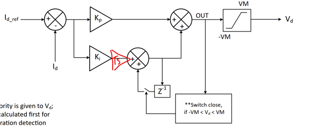
The second question is whether the discrete integrator is considering the discrete sampling time Ts? It is not visualized in the datasheet but I am quite sure it is. What is the discrete sampling time? I guess it depends on PWM_FREQ_OUT.

I am sorry if this information is already available somewhere.

Best regards,

Manuel

PS: I hope the datasheet gets updated as there are a lot of inconsistencies e.g. CURRENT_LOOP_KP is confused with CURR_LOOP_KP etc...

  • Hi Manuel,

    Are you referring to the current loop Kp and Ki values? if yes, MCF8329A calculates these values internally using motor phase resistance and inductance. Internal calculation uses pole-zero cancellation method to arrive the current loop constants.

    Kp = 2 × π × fCL_BW × L

    Ki = 2 × π × fCL_BW × R

    where
    • KP is the proportional gain
    • KI is the integral gain
    • fCL_BW is the current loop bandwidth (0.1 × ADC sampling frequency)
    • L is the motor phase inductance
    • R is motor phase resistance

    Yes, current sampling rate is based on the PWM frequency. 

    PWM switching frequency- fPWM (Khz) current sampling frequency (Khz)
    <15 fPWM
    20 to 30 fPWM/2
    35 to 60 fPWM/4

    Thanks,

    Dhinesh

  • Hi Dhinesh,

    thanks for answering, this is what I was looking for! Is this information available in a document which I did not find? 

    The second question is whether the discrete integrator is considering the discrete sampling time Ts= 1/ADC sampling freq? It is not visualized in the datasheet but I am quite sure it is as these are gains designed for continuous control.

    Something like this:


    Best regards,

    Manuel

  • Hi Manuel,

    Yes, Ts is inverse of current sampling frequency. 

    For MCF8329A, current sampling frequency vs PWM frequency table is slightly different. 

    PWM switching frequency- fPWM (Khz) current sampling frequency (Khz)
    <15 fPWM
    20 to 30 fPWM/2
    35 to 45 fPWM/3
    50 to 60 fPWM/4
    70 to 75 fPWM/5

    Thanks,

    Dhinesh

  • Thanks Dhinesh,

    but what I was referring to is that a discrete time integrator is dependent on Ts. Either it has to be considered in Ki (which I do not think as it is designed for a continuous controller)  or in Figure 6-27 ff the sampling time Ts is missing. Am I understanding it correctly, that it is not pictured but the internal algorithm is calculating like that?

    Best regards,

    Manuel

  • HI Manuel,

    You are right, Ts is not highlighted in the picture but device algorithm using it internally for calculation.

    Thanks,

    Dhinesh