Other Parts Discussed in Thread: DRV8824, DRV8461, DRV8434, DRV8436, DRV8452, DRV8424
Tool/software:
- I am debugging a DRV8824 circuit and am encountering oscillations ... I'd like to figure out where they are coming from.
- The circuit is implemented as per the DRV8824 datasheet, as is the layout. I've double-checked all components part numbers and they are correct. The board is 6 layers, with all of the layout as per the datasheet on L6, with just the four drive lines (AOUT1|2 and BOUT1|2) on L1 through vias from L6.
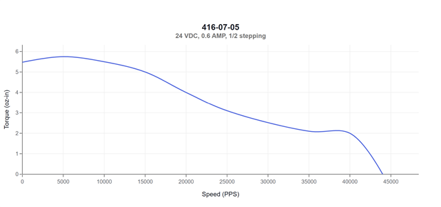
- The motor is a Lin Engineering WD-416-07-05 (0.6A/phase, 5.4Ohms/phase, running at 24V). I have also tried another motor from a radically different supplier, with very similar specs, and the results are the same.
- What I observe is this:
- The outputs AOUT1|2 BOUT1|2 oscillate when I enable the DRV8824 (i.e., the half-bridges are ON and see the motor) without commanding the DRV8824 to step. It also happens when stepping.
- If I use two 47Ohm power resistors in place of the stepper motor's two windings, I avoid the oscillations if I keep the power rail below 21V.
- If I connect either stepper motor, I get oscillations at all voltages I tested (12V up to 28V), once the DRV8824 is enabled, with or without commanding it to step.
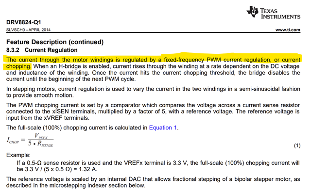
- My programmed current setting is (30k/(10k+30k))*3.3V/(5*0.82Ohms) = 600mA, AVREF and BVREF are verified to be 2.5V.
- When stepping in the non-oscillating condition with VMA = VMB = 14.4V, V_ISENA and V_ISENB are at around 0.24V, well below the DRV8824's xISENSE trip voltage of ~0.660mV. Once oscillating, the (DC) voltage on ISENSA|B drops to almost zero.
- VCP is very happy (e.g., 26V for a power rail of 14V).
- The (current) oscillations make their way all the way back to the external power supply; i.e. I see the current from the external PSU varying at the same frequency as the DRV8824's outputs, at twice the magnitude of an individual DRV8824 output.
- Various things I tried, to no avail:
- Increased the bulk capacitance to 220uF (from 20uF) -- no change.
- Used three different power supplies (one linear and two switching) to power VMA & VMB from 14.4V to 28V -- no change.
- Minimized inductance from the power supplies by twisting the power leads to the DRV8824 circuit -- no change.
- Varied the length of wire between the DRV8824 and the resistors or motor -- no change.
To repeat, I am seeing oscillations in a circuit that I believe has been implemented properly, with reasonably chosen components, even when I'm not stepping; i.e. the 'DC load' on the DRV8824 is driving it to oscillate.
I'm attaching the schematic and a bunch of screen captures with descriptions in the screen capture. Note that there are voltage and frequency measurements on the right side of the 'scope captures.
I'll also note that if the stepping is really slow (say, < 100steps/sec), the motor is able to step, since the oscillations only occur when the half-bridge is fully enabled; the phase windings are switching directions, and there is enough current to energize the windings in a static sense and perform a step. But faster stepping at higher rates is impossible.
I'd appreciate help in resolving this -- am happy to create additional test scenarios, capture additional probe points, etc.
Thank you,
Schematic:

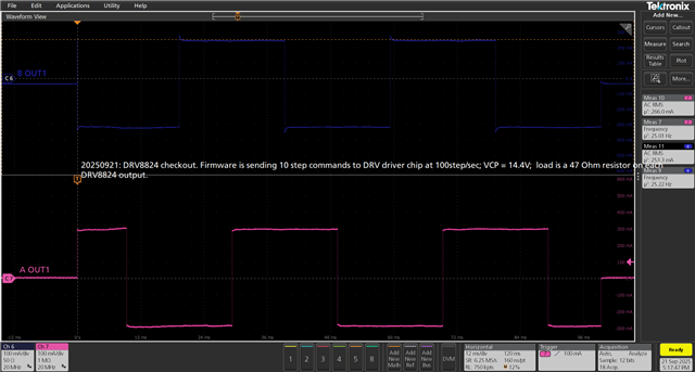
DRV8824 NOT oscillating when driving 47Ohm resistors in place of stepper motor, and power rail = 14.4V, stepping at a very slow speed:
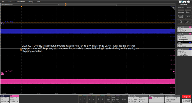
Now with stepper motor attached, power rail = 14.4V, no stepping, DRV8824 outputs are oscillating:
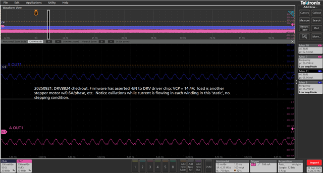
Closeup of oscillation:
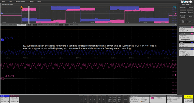
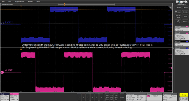
Stepping at slow speed, power rail = 14.4V, with stepper motor connected:
Another view of slow-stepping with oscillations, zoomed in on the oscillation: