DRV8711: DRV8711: 4-channel design – Drivers #1 & #3 no PWM, Driver #4 fault, only #2 working

Part Number: DRV8711
Other Parts Discussed in Thread: , CSD18502Q5B, , CSD18531Q5A

Tool/software:

Hello Team,

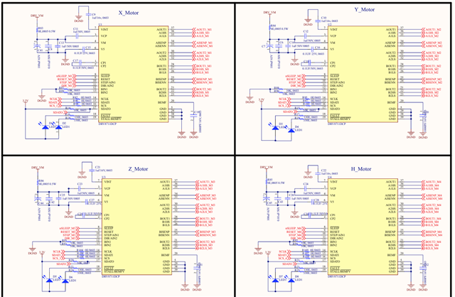
We have designed a 4-channel motor driver board using DRV8711 + external MOSFETs (Vishay SQJ952EP-T1_GE3) to drive 24 V stepper motors (each motor up to ~10 A).
In our testing, we are observing different behavior on each driver:

  • Driver #1 → Not generating PWM at the outputs. No motor movement.

  • Driver #2 → Working fine, motor runs normally.

  • Driver #3 → Not working. When monitoring the motor winding voltages:

    • Winding1 = 0 V

    • Winding2 = 24 V (stuck high)

  • Driver #4 → PWM is generated, but when we connect a motor, the driver goes into FAULT condition immediately.

So effectively, only Driver #2 is functional, while #1, #3, and #4 fail in different ways.

Our setup:

  • 24 V supply input

  • DRV8711 (4x, each channel has its own driver IC + MOSFETs)

  • Shared SPI bus for configuration (chip select separated)

  • External MOSFETs: SQJ952EP-T1_GE3

  • Current sense resistors = 50mΩ

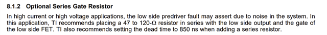
  • Gate resistors = 10Ω

  1. What could cause no PWM output on Driver #1 and #3, even though SPI configuration is correct?

  2. Why does Driver #3 output 0 V on one winding and 24 V stuck on the other? Could this indicate a MOSFET short or DRV8711 internal issue?

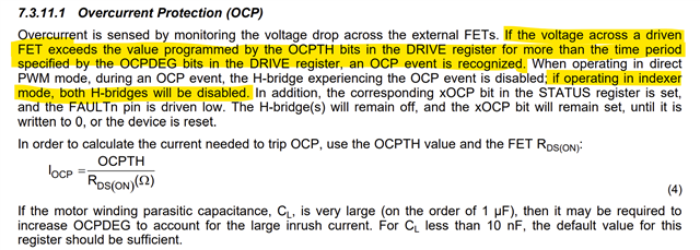
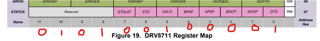
  3. On Driver #4, what could trigger a FAULT as soon as motor is connected (overcurrent, gate drive issue, MOSFET suitability)?

  4. Are there any recommended debug steps to isolate whether the issue is in DRV8711 IC configuration, gate drive, or MOSFET hardware?

Any guidance or debug procedure will be very helpful.

  • Hi Upendra,

    Thanks for contacting us.

    For debug you must read the STATUS register and see what the exact fault that happened. Any of the fault bits set except for the stall related bits7 and 6 will disable the outputs. Most likely a APDF or BPDF could be the reason. Please check and provide the STATUS register output for each of the drivers. For future investigation we would need all the register settings for a device. 

    Also double check if you have correctly set the TDRIVEN,P and IDRIVEN,P as required to support the FETs in your board. See section 8.1 Application Information in the datasheet for calculations. For some use cases follow the guidance ins section 8.1.2 Optional Series Gate Resistor

    This product has been shipping to customers since 2013. Proper configuration is important. If you continue to get APDF or BPDF you may want to try increasing IDRIVEN,P and TDRIVEN,P settings as well as use the optional series gate resistor value for the low-side FETs. Thank you.

    Regards, Murugavel 

  • Hello,

    I am designing a 4-channel motor driver using the DRV8711 for a stepper motor application.

    • Motor supply voltage (VM): 24 V

    • Motor current: up to 15 A (per channel)

    • Power supply: 24 V DC

    I tested my design with two different MOSFET types, but both did not work properly. However, the BOOST-DRV8711 EVM (with CSD18502Q5B MOSFETs) works fine with the same register configuration.

    My designs tested:

    • Design 1: AOD442 MOSFETs

    • Design 2: SQJ952EP-T1_GE3 MOSFETs

    Both designs showed issues (PWM not stable / not running properly), while the EVM worked fine under the same register settings.

    My questions are:

    1. Does the DRV8711 require any specific MOSFETs, or can I use any N-channel MOSFETs as long as they meet voltage/current ratings?

    2. What ranges of Vds, Rds(on), and gate charge (Qg/Ciss) are recommended for reliable switching with DRV8711?

    3. Since my application requires 24 V / 15 A, could you suggest suitable TI MOSFETs (or design guidelines) that can handle this current while being well-matched to the DRV8711’s gate driver capability?

    4. Is there any application note or design document specific to MOSFET selection for DRV8711?

    I would appreciate your guidance to select the right external MOSFETs for stable operation at 15 A motor current.

    Thanks & regards,
    Upendra Talluri

  • Hi Upendra,

    Thanks for the follow up.

    My questions are:

    1. Does the DRV8711 require any specific MOSFETs, or can I use any N-channel MOSFETs as long as they meet voltage/current ratings?

    2. What ranges of Vds, Rds(on), and gate charge (Qg/Ciss) are recommended for reliable switching with DRV8711?

    3. Since my application requires 24 V / 15 A, could you suggest suitable TI MOSFETs (or design guidelines) that can handle this current while being well-matched to the DRV8711’s gate driver capability?

    4. Is there any application note or design document specific to MOSFET selection for DRV8711?

    There is no separate document for MOSFET selection for the DRV8711 other than what we have provided in the datasheet. See section 8.1 Application Information in the datasheet for calculations. These calculations utilize  gate charge (Qg/Ciss) values for the specific MOSFETs considered. The TDRIVEN,P and IDRIVEN,P would vary for different FETs based on this calculated values. The settings for these for BOOST-DRV8711 EVM (with CSD18502Q5B MOSFETs) will not work with another vendor's FETs unless you change the register settings to the desired values from the calculation.

    It is possible some FETs may not be fully driven with the max settings for the TDRIVEN,P and IDRIVEN,P  register values. This would result with APDF and BPDF faults and cause a no output situation. When correct settings are used for TDRIVEN,P and IDRIVEN,P register values there should be no faults.  Most popular MOSFETs are covered by these settings range. I have seen customers use various vendor's MOSFETs successfully with the DRV8711 in their products. 

    Since my application requires 24 V / 15 A, could you suggest suitable TI MOSFETs (or design guidelines) that can handle this current while being well-matched to the DRV8711’s gate driver capability?

    You mentioned the BOOST-DRV8711 EVM (with CSD18502Q5B MOSFETs) works fine for your requirements. The CSD18502Q5B MOSFETs (up to 40 V) is capable of supporting your 24 V / 15 A requirement with no issues. Our DRV8711EVM uses the CSD18531Q5A MOSFETs (up to 60 V) which are also suitable for your application. Thank you.

    Regards, Murugavel 

  • Thank you for your previous reply and support. I am currently working on a 4-channel motor driver design using the DRV8711 along with SQJ952EP-T1_GE3 MOSFETs. I would like your assistance in verifying my register configuration and implementation.

    with this setting BOOST-DRV8711 is working fine.

    Below is the code Register Settings for motor control and snippet for status monitoring and :

    Register Function Parameter Value Value/Configuration Description
    CONTROL deadtime=1, microsteps=16 ((1 & 3) << 10) | ((4 & 0xF) << 3) | DRV8711CTL_IGAIN_10 | DRV8711CTL_STALL_INTERNAL Deadtime=1, Microsteps=16 (code=4), Internal gain=10, Internal stall detection
    TORQUE drive=120 DRV8711TRQ_BEMF_50us | 120 Back-EMF sample time=50μs, Drive current=120
    OFF - DRV8711OFF_STEPMOTOR | (0x030 & DRV8711OFF_OFFTIME_MASK) Stepper motor mode, Off time=0x030
    BLANK - DRV8711BLNK_ADAPTIVE_BLANK | (0x80 & DRV8711BLNK_BLANKTIME_MASK) Adaptive blanking enabled, Blank time=0x80
    DECAY decay_mode=3 (3 & 7) << 8 | (0x20 & DRV8711DEC_DECAYTIME_MASK) Decay mode=3, Decay time=0x20
    STALL - DRV8711STL_DIVIDE_8 | DRV8711STL_STEPS_1 | (0x20 & DRV8711STL_THRES_MASK) Clock divide=8, Step threshold=1, Stall threshold=0x20
    DRIVE gate_speed=1, gate_drive=1 ((1 & 3) * 0x500) | ((1 & 3) * 0x050) | DRV8711DRV_OCP_1us | DRV8711DRV_OCP_250mV Gate drive=1×0x500, Gate speed=1×0x050, OCP time=1μs, OCP threshold=250mV
    STATUS - 0 Cleared to reset any fault conditions

    uint16_t status = DRV8711_GetStatus(&stepper1);
    printf("DRV8711 Status: 0x%04X\n", status);

    // Optional: decode specific faults for clarity
    if (status & 0x0080) printf(" - Overtemperature fault\n");
    if (status & 0x0040) printf(" - Channel A overcurrent\n");
    if (status & 0x0020) printf(" - Channel B overcurrent\n");
    if (status & 0x0010) printf(" - Channel A predriver fault\n");
    if (status & 0x0008) printf(" - Channel B predriver fault\n");
    if (status & 0x0004) printf(" - Undervoltage lockout\n");
    if (status & 0x0002) printf(" - Stall detected\n");
    if (status & 0x0001) printf(" - Latched stall\n");

    Could you please review this configuration and confirm if it is correct for proper operation with the SQJ952EP-T1_GE3 MOSFETs?
    Also, kindly suggest if any register modifications or parameter adjustments are recommended for reliability and safe operation.

    Looking forward to your guidance.

    Thanks & Regards

    Upendra

  • I am testing with four BOOST-DRV8711 EVM boards (used together in a 4-channel setup). The motors are running normally, but when I read the status registers via SPI, I see error flags on two of the boards.

    Readings:

    • Board 1: Status = 0x0000 → No error

    • Board 2: Status = 0x0000 → No error

    • Board 3: Status = 0x0521 → Reports Channel B overcurrent + Latched stall

    • Board 4: Status = 0x0521 → Reports Channel B overcurrent + Latched stall

    Even with these reported faults, the motors on boards 3 and 4 continue to run correctly.

    My questions:

    1. Why do two of the BOOST-DRV8711 boards show status = 0x0521 while still operating normally?

    2. Are these fault bits (Channel B overcurrent, Latched stall) sometimes triggered during normal operation, or could this be related to SPI read timing or interaction between multiple boards?

    3. Is there a recommended method to interpret or filter these status bits when using multiple DRV8711 devices in the same system?

    4. Do these flags indicate a real condition that requires corrective action, or can they be safely ignored if the driver is otherwise operating correctly?

  • Hi Upendra,

    Could you please review this configuration and confirm if it is correct for proper operation with the SQJ952EP-T1_GE3 MOSFETs?
    Also, kindly suggest if any register modifications or parameter adjustments are recommended for reliability and safe operation.

    Did you get a chance to calculate the register parameters for your non-TI MOSFETs using the formulae in section 8.2.2.3 Support External FETs? What values did you get, please share these with us. If you have any questions regarding the formulae feel free to let us know. We do not design end products. We support with all the necessary information and guidelines required to use our device in any application. If you have a specific problem with configuration we're happy to help. 

    Readings:

    • Board 1: Status = 0x0000 → No error

    • Board 2: Status = 0x0000 → No error

    • Board 3: Status = 0x0521 → Reports Channel B overcurrent + Latched stall

    • Board 4: Status = 0x0521 → Reports Channel B overcurrent + Latched stall

    Even with these reported faults, the motors on boards 3 and 4 continue to run correctly.

    My questions:

    1. Why do two of the BOOST-DRV8711 boards show status = 0x0521 while still operating normally?

    Because the motor is operating normally, it does not appear to be an overcurrent OCP event. See below from the datasheet. An OCP detection would disable the outputs.

    You mentioned the STATUS was 0x0521. Plugging in this value to the bit fields of the STATUS register, I get a different inference. BIT0 is OTS, over temperature, set. However the motor was running normally. This means an OTS did not happen. Same thing with BIT5, which is UVLO, under voltage. This means the VM power rail went below UVLO threshold. If it was a real UVLO condition the motor will not operate. I suspect, your microcontroller may be having an erratic SPI transaction and reading incorrect bit values, perhaps due to incorrect SPI configuration.  

    Can you check the SPI transactions with an oscilloscope or an SPI analyzer and send the captures for review? They must be in compliance as below. If register write with SPI was the problem this could be the reason why your MOSFETs were not driven correctly because the settings may have been what you wrote to the registers. Let's verify this and confirm first. Also the RESERVED bit fields are usually 0 but you were reading them to be 0x5 (0x521). 

    uint16_t status = DRV8711_GetStatus(&stepper1);
    printf("DRV8711 Status: 0x%04X\n", status);

    // Optional: decode specific faults for clarity
    if (status & 0x0080) printf(" - Overtemperature fault\n");
    if (status & 0x0040) printf(" - Channel A overcurrent\n");
    if (status & 0x0020) printf(" - Channel B overcurrent\n");
    if (status & 0x0010) printf(" - Channel A predriver fault\n");
    if (status & 0x0008) printf(" - Channel B predriver fault\n");
    if (status & 0x0004) printf(" - Undervoltage lockout\n");
    if (status & 0x0002) printf(" - Stall detected\n");
    if (status & 0x0001) printf(" - Latched stall\n");

    The order of the bits are reversed in your "Optional: decode specific faults" code. OTS is BIT0 of the STATUS register. Latched Stall detect is BIT7. In the future when you send register contents for review, please send the programmed hex values for each of the registers bit values. This will help avoid misinterpretation.  

    Because of the reason the order of the bits were changed in this piece of code, can you check if all the registers' programmed values were of correct order? 

    Are these fault bits (Channel B overcurrent, Latched stall) sometimes triggered during normal operation, or could this be related to SPI read timing or interaction between multiple boards?

    No, overcurrent will never be triggered unless there is a real overcurrent and when an overcurrent is triggered the motor will not be driven. This looks like an SPI read issue. This needs to be fixed. If you're using SPI, SCLK > 1 MHz you may want to bump it down to 500 kHz. 

    Is there a recommended method to interpret or filter these status bits when using multiple DRV8711 devices in the same system?

    As long as the specified SPI timing requirements are met for each device there should be no issues with SPI communication. 

    Do these flags indicate a real condition that requires corrective action, or can they be safely ignored if the driver is otherwise operating correctly?

    These flags are not expected without a real issue. This should be fixed. I do not recommend ignoring errors. The only error that may be inconsequential is the STALL detection. If the threshold is not properly configured it would incorrectly detect a stall. A STALL detection does not disable the running the motor. Internal stall detection can be disabled by setting EXSTALL bit to 1 in the CTRL register. 

    Regards, Murugavel