Other Parts Discussed in Thread: DRV8706-Q1
Tool/software:
Good morning, TI experts.
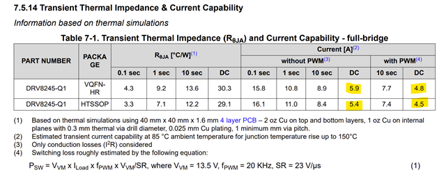
I'm using a DRV8245 in an application with a brushed DC motor. This motor operates at 13.7 volts, with a nominal current of 10 amps. I wanted to know if the chosen driver is suitable for this motor.
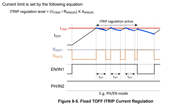
I'd also like to know if, using the IPROP system and external resistor, it's possible to read any current flowing from the motor to the H-bridge. This is because in my application, the motor has a high moment of inertia. Therefore, to decelerate the motor in a controlled manner, I need to read the current from both the bridge to the motor and the motor to the bridge. Reading the driver datasheet, I understand that current measurement is only possible from the driver to the motor.
Can you confirm?
Regards