


Tool/software:
Hello, I am using the mct829a in a custom pcb to run a water pump and have encountered a couple issues. On our custom board, we seem to be getting some strange outputs from the DACOUT analog signal pin and have tried many things to resolve the issue to no avail. Here is the current schematic of MY board, as compared to the evaluation board TI makes:
MY board: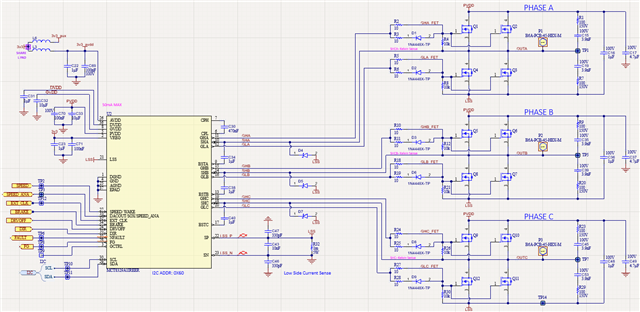
My board current DNP schematic: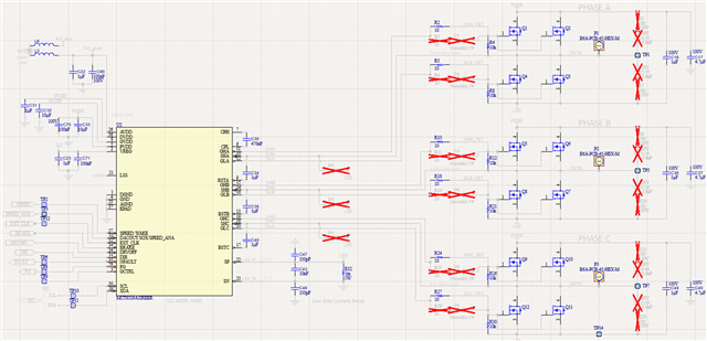
TI board:
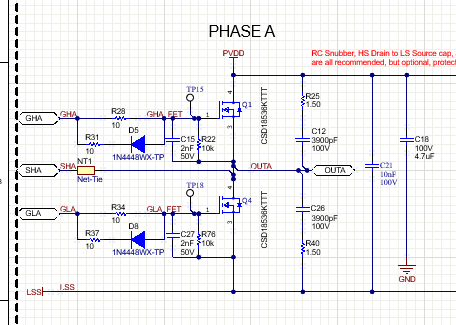
I would like to point out the only difference in schematics seem to be our AVDD and Vreg having a 1 uF instead of 10uF, as well as the DNPd diode on the incorrect pin for the fet driver outputs. We also have two mosfets in parallel for each high side and low side per phase instead of just one.
I also want to note the exact same mosfets are used.
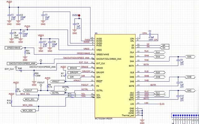
the dacout pin connects directly to our stm32 pin (no filters, etc), not shown.
With that provided, let me get into the issue we are facing. when we are running a motor, we are getting dacout to look as shown: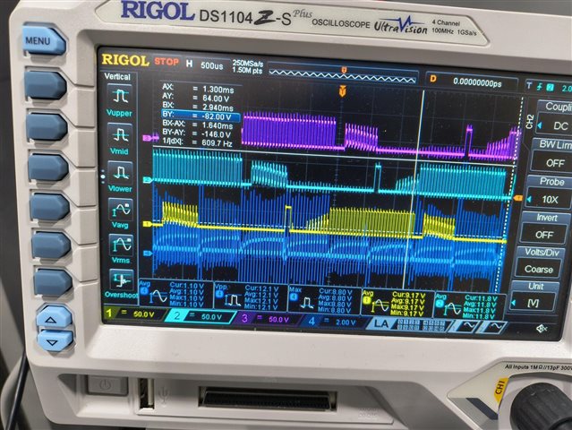
dark blue is dacout, pink, light blue, and yellow are the different phases.
Here is another oscope view with only one phase for better visibility.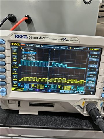
yellow is dacout, blue is a phase
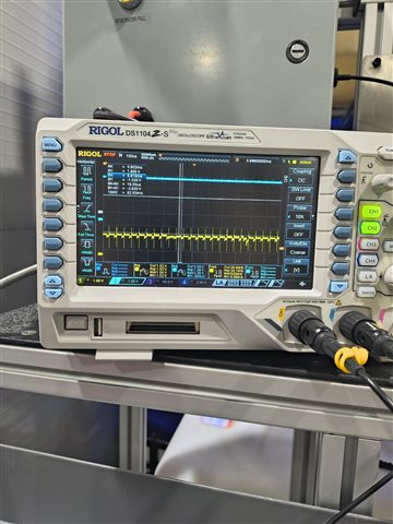
Compare this with the evaluation board dacout:
I have spend quite a while trying to get to the bottom of this issue, but have been unsuccessful this far.
Here is what I have done to try to fix the issue.
hardware level
- replace 1 uF on AVDD and Vreg with 10uF
- replace 10 ohm gate resistors with 51 ohm
- increase Cgvdd from 10uF to 20uF
- increase Cbstx from 1uF to 2uF
- removed gate connection to parallel mosfets so only one mosfet is used for each high and low side for each phase to match eval board
firmware level
-use same values for our boards mct8329a registers as the default values on eval board (when applicable)
- change switching frequency, kp and ki values (we are using speed loop)
here are the register values we are using on our board:
const uint32_t mct8329a_defaults[MCT8329A_NUM_REG] =
{
0x2340EDC2, //0x80 ISD_CONFIG
0x3D53D700, //0x82 MOTOR_STARTUP1
0x0C25246B, //0x84 MOTOR_STARTUP2
0x0025E21E, //0x86 CLOSED_LOOP1
0x0AA3FF68, //0x88 CLOSED_LOOP2
0x34FFF800, //0x8A CLOSED_LOOP3
0x1AC953, //0x8C CLOSED_LOOP4
(0x80000011 |(0b0100000000 <<20)|(0b000010000000 << 8)), //0x8E CONST_SPEED kp and ki live here... Kp,Ki working last:0x80700711
0xE530C80, //0x90 CONST_PWR 1000Hz 1KW
0x70B25644, //0x92 FAULT_CONFIG1
0x3CE6200E, //0x94 FAULT_CONFIG2
0x24DB7200, //0x96 F150_DEG_TWO_PH_PROFILE
0x48DB6946, //0x98 F150_DEG_THREE_PH_PROFILE
0x032184A6, //0x9A REF_PRIFILES1
0x34C80AFC, //0x8C REF_PRIFILES2
0x4787D70C, //0x8E REF_PRIFILES3
0x000C9932, //0xA0 REF_PRIFILES4
0x1F6BF200, //0xA2 REF_PRIFILES5
0x00708000, //0xA4 REF_PRIFILES6
// 0x20600004, //0xA6 PIN_CONFIG1 I2C Speed,
0x2E700002, //0xA6 PIN_CONFIG1 PWM
0x1E0020AA, //0xA8 PIN_CONFIG2
0x27100008, //0xAA DEVICE_CONFIG deadtime=400na
0x000200FF, //0xAC GD_CONFIG1
0x00000000}; //0xAE GD_CONFIG2
We are also experiencing an issue where the speed will be very stable if we set it to something, but if we set it to a lower speed, or slow to stop, it will be very smooth like 85% of the time, but the other 15% it will dramatically stop, then immediately resart spinning really fast before it will slow down more smoothly. I don't know if that issue is related to the Kp Ki values, or if this weird speed/current reading is causing the speed loop to be confused.
I am kind of lost on how to move forward. Any advice or help is appreciated!! Let me know if I can provide any more information to help reach some sort of resolution.
