DRV8262: choose a resistor for OCP

Part Number: DRV8262


Hello,

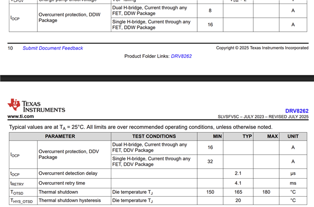
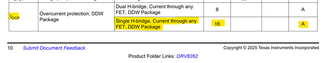
On my current design a choose a DRV8262DDW, it's a single H bridge. On datasheet, the internal current sense is connected together only for single H bride. in this case, the OCP is set for both NMOS (I suppose that, it's difficult to understand the behavior of internal mirror current)

I have a question about resistor calculation IPROPI. On my design a put a single resistor 3.3K to GND. In this case, I suppose that the OCP is set at 4.71A for OUT1 and OUT2. is it true or false ?

I would like set the OCP at 8A for OUT1 and OUT2, could you calculate the resistor ?

Thank for your help

Best regards

  • Hi Douchan,

    Thank you for your post.

    There are two different entities regarding load current in the DRV8262. One is the Itrip based current limiting which uses external RIPROPI and VREF voltage to set the current. See below from the datasheet. The formula shows how this current limiting feature can be set.

    The second is the over current protection OCP which helps with output short circuit protection. The threshold for OCP is given in the IOCP specification - see below. The IOCP specification is hard coded and cannot be changed.


    The OCP is independent of the current limiting feature and does not depend on RIPROPI. See below. OCP has its own sensing on each of the output FETs both high side and low side. 

    I have a question about resistor calculation IPROPI. On my design a put a single resistor 3.3K to GND. In this case, I suppose that the OCP is set at 4.71A for OUT1 and OUT2. is it true or false ?

    I would like set the OCP at 8A for OUT1 and OUT2, could you calculate the resistor ?

    Assuming VREF = 3.3 V, with 3.3 kΩ RIPROPI the motor current would be limited to 4.71 A. This is the Itrip current setting not OCP. The motor inrush current or stall current would be limited to 4.71 A.

    You cannot use Itrip setting of 8 A because 8 A is the OCP over current threshold already. The maximum Itrip must be < IOCP specification. In addition the maximum Itrip current would also be a function of power dissipation of the device. Above a certain current depending upon the ambient temperature Ta the device can experience a thermal shutdown TSD. For this DDW package and proper PCB design and VM voltage used. See below current capability table. With two bridges in parallel current capability can be increased. 


    If the continuous current requirement for the application is 8 A the DRv8262 DDW may not be able to support it.

    Regards, Murugavel 

  • Hello Murugavel,

    thanks for your response and detail about internal OCP of device DRV8262DDW.

    See below the schematic with resistor 3.3K tied together on pin IPROP

    in my design, the current limitation is set a 4.7A for OUT1 and 4.7A for OUT2 ? (i understand it's not OCP. The OCP is set a 8A for canal OUT1 and 8A for canal OUT2 by internal structure and not possible to change)

    I would like to set the current limitation under OCP according to datasheet, for example 7.5A, is it possible ? and tell me what is the correct value of resistor IPROP 

    thank for your advice and technical support.

    Best regards

  • Hi Douchan,

    Thanks for sharing the schematic. You have connected MODE1 and MODE2 to DVDD, suggesting PWM control mode and Single H-Bridge configuration. I assume the outputs are connected together accordingly. 

    in my design, the current limitation is set a 4.7A for OUT1 and 4.7A for OUT2 ? (i understand it's not OCP. The OCP is set a 8A for canal OUT1 and 8A for canal OUT2 by internal structure and not possible to change)

    In your current schematic, VREF = 3.3 V, RIPROPI = 3.3 kΩ. This calculates to Itrip = 4.72 A. Because you are using Single H-Bridge mode the IOCP is 16 A , it is 8 A for dual H-Bridge mode. 

    I would like to set the current limitation under OCP according to datasheet, for example 7.5A, is it possible ? and tell me what is the correct value of resistor IPROP 

    I take you want Itrip current limiting for 7.5 A. In this Single H configuration this is possible. 7.5 A load current would translate to 7.5 / 212E-6 = 0.00159 μA on IPROPI. To convert this to 3.3 V the resistance value required would be 3.3 / 0.00159 = 2.075 kΩ - you can use a closest available 1 % or less tolerance resistor. This would set Itrip to approx. 7.5 A. Per the transient thermal impedance table, keep in mind the device can drive 7.5 A for about 10 to 15 seconds. It can support a continuous current of close to 5 A with proper PCB thermal design. 

    Regards, Murugavel 

  • Hi Murugavel,

    thanks you so much for your technical support !

    on my design, the DCDC motor is connected between OUT1 and OUT2 and I set the slow decay mode. The internal resistor of motor is 4 ohms and inductor 300µH and maxi voltage 24V. I dont have the backEMF value

    I understand that => if resistor increase, the current limitation decrease. OCP stay the same, in this case 16A per each internal NMOS.

    But it's difficult to understand if this limitation is set for each internal NMOS or not. Question => the current of motor is limited at 4.7A or (4.7A x 2) ?

    Best regards

  • Hi Douchan,

    on my design, the DCDC motor is connected between OUT1 and OUT2 and I set the slow decay mode. The internal resistor of motor is 4 ohms and inductor 300µH and maxi voltage 24V. I dont have the backEMF value

    This is fine. I just wanted to make sure all the OUT1 and OUT2 are connected together. See below.

    I understand that => if resistor increase, the current limitation decrease. OCP stay the same, in this case 16A per each internal NMOS.

    Perfect!

    But it's difficult to understand if this limitation is set for each internal NMOS or not. Question => the current of motor is limited at 4.7A or (4.7A x 2) ?

    The current limit is for load current only and not for each internal NMOS. See below. So with the value of RIPROPI = 3.3 kΩ the load current will be limited to 4.7 A. For Itrip current limiting purpose current sensing is done on the high-side FETs only. Because the FETs are connected in parallel the current is evently distributed between the two FETs. When Itrip is configured for 4.7 A, each FET passes 4.7/2 = 2.35 A. The IPROPI are connected together which adds 2.35 + 2.35 = 4.7 A. I hope this gives clarity on how it works.  

    With RIPROPI = 2 kΩ the load current limit would be 7.5 A. Each HS-FET would pass 3.75 A. 

    The OCP overcurrent architecture is different. For each NMOS it is 8 A. When connected in parallel for Single-H the OCP limit at the OUTx pins double to 16 A.  

    Regards, Murugavel 

  • ok thanks for all detail. I will put several information and equation inside my design justification.

    Best regards

    Douchan