


I'm relatively new to motor control. I have had an existing design that appeared to be functioning properly, that I borrowed from a previous design used in a similar application. However, I've recently had to change my motor winding impedance from 20Ω to 40Ω. I am noticing that the DRV8811, with the new motor coil, does not seem to have enough time to ramp all the way up to the current limit I’ve set before I need to step the motor to the next position, and there doesn’t seem to be any way to adjust the time rate of change of the current through the coil. I am wondering:
- Am I right when I say there is no way to increase the “ramp-up” speed of the current through the motor winding
- Is 40Ω, or 20Ω for that matter, a large, average, or small impedance for the coil. I didn’t think much on it until now, but that seems like those might be large numbers
- Is there perhaps another issue I’m fighting with, and don’t have enough experience to notice it yet.
I’ve attached some waveform images below, for reference. They were taken with a fairly old HP scope and a passive 1x probe, so I might not be noticing all the details. From the images, it appears that I don’t really enter decay mode, with the exception of when I’m microstepping, and it seems like the driver is being slammed off (ie, no decay). I have also noticed, though, that the times for decay and blanking are seemingly on a different scales than my charge time, which is concerning me as well. I’ve checked the rest of the circuit, and I believe it’s set up properly (for slow decay operation). Thanks in advance to anyone with some advice for me.
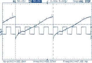
CH1: Voltage across RSENSE_A
CH2: Step Input (Half-step)
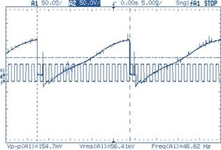
CH1: Voltage across RSENSE_A
CH2: Step Input (Eighth-step (microstep))
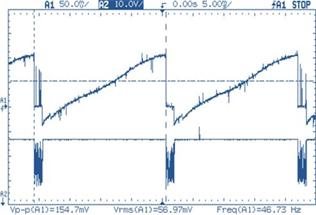
CH1: Voltage across RSENSE_A
CH2: Voltage at RCA (Decay voltage)
vREF: 2.5V
rISENSE: 0.39Ω
iCHOP: 0.801A
Rx: 4.75E+04Ω
Cx: 8.20E-10F
tOFFx: 3.90E-05s
38.95μs
25.67kHz
tBLANKx: 1.15E-06s
1.15μs
871.08kHz
vCC: 5V
vDECAY: 5V
Using:
Slow Decay
vSR: 0V - Synchronous Rectification


