This thread has been locked.

If you have a related question, please click the "Ask a related question" button in the top right corner. The newly created question will be automatically linked to this question.

DRV8714-Q1: Solenoid driver

Part Number: DRV8714-Q1

Hi team,

My customer is searching for a solenoid driver for CDC suspension, the requirements as below:

  1. There is no PWM resource from MCU, so they need PWM generator in the driver;
  2.  >=20kHz frequency
  3. 4 channels
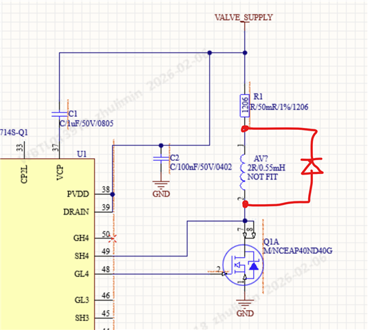
  4. 5A current capability, external MOS is also accepted
  5. VDS monitor

DRV8714 maybe a good solution for the most specs, but there is no PWM generator in the device, customer need to continuesly refresh HBX_PWM to change the high/low status, we need to check is it ok to use this scheme to simulate the PWM, is there frequency limit? How about the effect? Anything take care?

Or is there any better solutions?

Thanks

BR,

Daniel

  • Hi Daniel,

    DRV8714 maybe a good solution for the most specs, but there is no PWM generator in the device, customer need to continuesly refresh HBX_PWM to change the high/low status, we need to check is it ok to use this scheme to simulate the PWM

    Yes this could simulate an INx on/off duty cycle. It requires continuous SPI transactions at a fast rate. 

    is there frequency limit? How about the effect? Anything take care?

    At 20 kHz desired PWM, the SPI writes one for on and another for off must happen with 50 μs period. This would be 2x 16-bit SPI operations with 25 μs period each. Accounting for time between the two let's say 20 μs period may be needed for 16 CLKs, each SCLK would have to be ≤ 1.25 μs period or ≥ 800 kHz. While this can be supported by the DRV8714-Q1 SPI because its SCLK spec is up to 10 MHz, it may be difficult for the controller to keep up with this level of periodic predictable timing with each writes. 

    Regards, Murugavel 

  • Hi Murugavel,

    For DRV8714, the customer wants to use only the low-side MOS of the half-bridge for driving, with the high-side floating, as shown in the figure below. When driving with PWM, will the high-side report a VDS fault? Is there a way to mask the VDS detection for the high-side without affecting the low-side detection?

    If configure as Vds disable mode, all the half bridge 1-8 will be disabled, including low side, any method to disable high side Vds only?

     Any other considerations when use DRV8714 as low side driver. Do they need to connect GH4 and SH4 to VALVE_SUPPLY to avoid the report Vds fault mistakenly?

    Thanks!

  • Hi Daniel,

    For DRV8714, the customer wants to use only the low-side MOS of the half-bridge for driving, with the high-side floating, as shown in the figure below. When driving with PWM, will the high-side report a VDS fault? Is there a way to mask the VDS detection for the high-side without affecting the low-side detection?

    There should be a free-wheeling Schottky diode for driving inductors - see below. 

    Since the solenoid is connected across SH4 and DRAIN, the VDS voltage would be the voltage across the solenoid coil. With a PWM when HS-FET is conducting (GHx driven) LS-FET would be off. The voltage across the coil should be very low once the free-wheeling diode dissipates the inductive kick-back voltage (should happen fast enough). Setting the VDS HS-FET 4 threshold to a high enough value could avoid a VDS tripping. Can you try this?

    The DRV8714-Q1 has a Split HS and LS Solenoid Control mode for driving a solenoid. 

    If configure as Vds disable mode, all the half bridge 1-8 will be disabled, including low side, any method to disable high side Vds only?

    There is no way to mask or ignore HS VDS tripping independently of the LS VDS detection. VDS looks at one half-bridge level.

    Any other considerations when use DRV8714 as low side driver. Do they need to connect GH4 and SH4 to VALVE_SUPPLY to avoid the report Vds fault mistakenly?

    Unused GHx must be left open. There's a potential for VGS fault because of no FET. Yes SH4 should be connected to the valve and drain of the LS-FET as shown in the schematic already. 

    Regards, Murugavel