This thread has been locked.

If you have a related question, please click the "Ask a related question" button in the top right corner. The newly created question will be automatically linked to this question.

DRV8873: DRV8873 Schematic Review

Part Number: DRV8873

Hello everyone,

I am currently designing a compact, high-performance mobile robot using the DRV8873 (DRV8873HPWPR) in hardware mode to drive a single brushed DC motor powered from a 7–12 V battery (VM). The motor driver is controlled by an STM32F103C8T6 (3.3 V logic), and the main objectives are fast acceleration, strong braking, and robustness under dynamic load conditions.

In my design:

  • VM (pins 13 and 20) is supplied from the battery with local 0.1 µF ceramic capacitors on each VM pin, plus a bulk capacitor (50 µF) placed close to the device, as recommended in the datasheet.

  • DVDD (pin 1) is powered from the MCU 3.3 V rail and decoupled with a 1 µF capacitor to ground.

  • The charge pump pins (CPH, CPL, VCP) are connected according to the datasheet using 47 nF (CPH–CPL) and 1 µF (VCP–VM) capacitors.

  • The exposed thermal pad (EPAD) and all GND pins are tied to a solid ground plane.

  • I am using IPROPI1/IPROPI2 to monitor motor current. A 620 ohm sense resistor converts the IPROPI current to voltage, followed by an RC filter (100 ohm / 1 nF) before feeding an ADC input on the STM32.

  • MODE is tied to GND to select hardware control mode.

  • NOL is tied to GND to enable open-load diagnostics at power-up.

  • NFAULT is pulled up to DVDD with 10 kohm and connected to a GPIO for fault monitoring.

  • SR (slew rate) is set using a resistor to ground to balance EMI and switching performance.

I would appreciate a review of the power pins, control pin configuration, and IPROPI current-sense network, and confirmation that the schematic follows TI’s recommended practices for the DRV8873 in this type of application. Any feedback regarding robustness, EMI considerations, or improvements is very welcome.

Thank you in advance for your support.
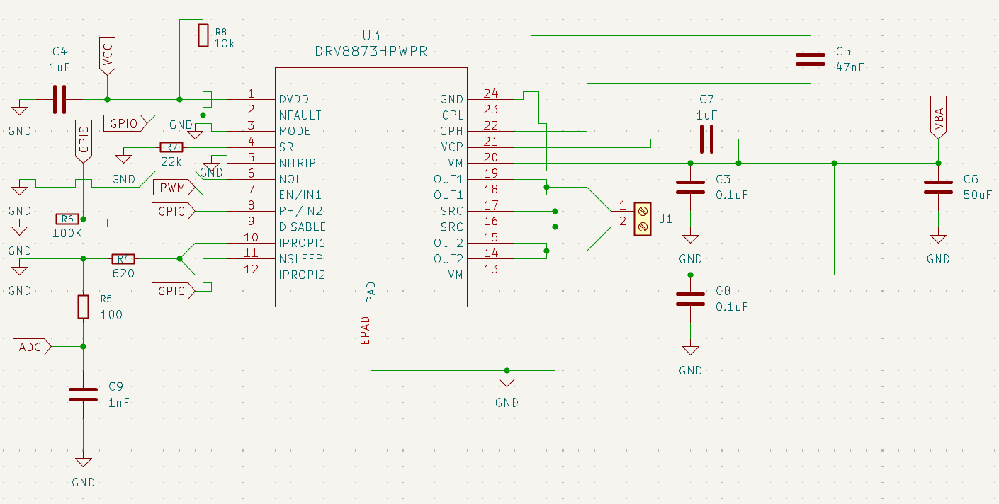
image.png

  • Hello,

    Overall the schematic and connections look good.

    From the power supply side, one important consideration is having enough bulk capacitance. As a general guideline, using at least 1uF to 4μF of capacitance for each Watt of motor power is considered good practice. With 12V of supply voltage and an RIPROPI = 620Ω which leads to a current regulation threshold of around 8.9A. This would indicate a good range of bulk cap falling in the 108uF to 432uF range. 

    The fastest slew rate setting is selected by setting the SR pin to ground. This can be fine, depending on the load, but if any EMI or ringing is observed on the switch node then it would be recommended to reduce the slew rate. 

    Best,

    David

  • Hello David,

    Thank you for the detailed explanation and guidance.

    Based on your recommendation regarding bulk capacitance sizing (1–4 µF per watt of motor power), I have updated the design to use a 330 µF bulk capacitor on the VM rail (rated ≥25 V, low ESR), placed close to the VM pins. The local 0.1 µF ceramic capacitors on each VM pin are kept as recommended in the datasheet.

    Regarding the slew rate, I decided to use a 22 kΩ resistor on the SR pin instead of tying it directly to ground. This provides a moderate slew rate to help reduce EMI and ringing while still maintaining good switching performance for the motor.

    Thanks again for your support and confirmation. This feedback is very helpful as I finalize the schematic before moving to PCB layout.

    Best regards,
    Ayoub

  • Hi Ayoub,

    Glad to help!

    Best,

    David

  • Hello David,


    Thank you for reviewing the schematic and for the confirmation.


    Best regards,
    Ayoub