Dear Sirs,
I designed a circuit with DRV8825 chip to drive bipolar stepper motor with U=3.9V and I=0.6A, step=1.8 deg.
For begining I have bought DRV8825 EVM, installed soft.
I used full step regime, reference value Vref=0.48V (Rsen=0.2 Ohm for this EVM), 1000 PPS, Vm=9V. Other parameters
were in the default state.
But when I switched up the motor it sounds very noisy and warms up!
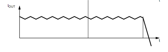
I connected oscilloscope to the output pins of the EVM and see very strange (for my opinion) picture - the base
signal from B-,B+,A-,A+ was modulated by high frequency pulses (near 31 kHz like switching ITRIP frequency).
Moreover the value of the amplitude of the output signal was 9V, but I hope i would be near 4V (as my motor need). I
tested IsenA, IsenB output and saw that voltage on sense resistors is modulated too.
What can it be? How should I use this IC to control my step motor without this modulation?
Below I attached some pictures.
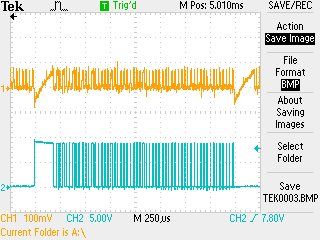
CH1=IsenA, CH2=Aout1
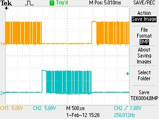
CH1=Aout1, CH2=Aout2
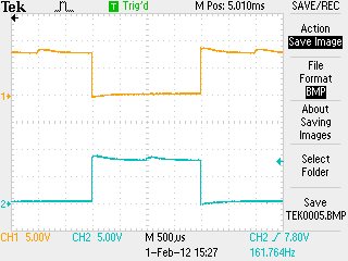
I can increase Vref to stop current control, Vref=1.72 V. Modulation disappeared, but in this case my motor will burn! Below I attach picture with Vref=1.72V
CH1=Aout1, CH2=Aout2
Alexey