


Part Number: DRV8353
Hello,
I am designing a 3-phase BLDC motor controller using the DRV8353. I want to implement a custom overcurrent protection (OCP) using an external non-inverting amplifier, but I am concerned about the DRV8353 operation.
[The Setup]
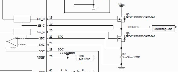
Shunt Configuration: I want to use a fixed-value shunt resistor between the Low-side MOSFET Source and GND.
Current Sensing: The voltage across the shunt is fed into an external non-inverting amplifier because the raw shunt voltage at my target current(set to overcurrent) is too low for the OCP response. [For example, the shunt resistor is 0.1ohm and overcurrent is 2A. And then, the voltage at the shunt resistor is 0.2V. But if the OCP voltage is 0.5V, OCP will not work. So I want to use amplifier to boost 0.2V to 0.5V.]
[The Core Question]
If I use an external amplifier in this way, the voltage potential at the SPx (and consequently the low-side internal Gate Driver Source in the DRV8353) will differ from the actual physical Source voltage of the low-side external MOSFETs.
Potential Mismatch: If there is a voltage difference (e.g., 0.1V ~ 0.3V) between the actual MOSFET Source and the SPx pin due to the external amplifier, will this cause instability of the gate drive stage?
Allowable Range: Is there a maximum allowable voltage offset between the actual MOSFET Source and the SPx reference before gate drive performance degrades or the device is damaged?
