This thread has been locked.

If you have a related question, please click the "Ask a related question" button in the top right corner. The newly created question will be automatically linked to this question.

DRV110: DRV110 Instability When Operating Above 56VDC

Part Number: DRV110

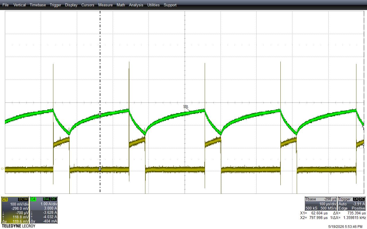
I'm driving a brake module which acts much like a solenoid...  The circuit operates from 24VDC to 80VDC but the DRV110 Vin is provided by a 15V regulator...  The circuits works as expected until the voltage is between 57V and 80V...  At that voltage the DRV110 becomes unstable and appears to be ringing...  I've attached the waveform for 56V and the one at 57V for comparison...  Note the green trace is current at the brake, the yellow is the voltage at the current sensing resistor...   The current is upside down...

Dave Beaty
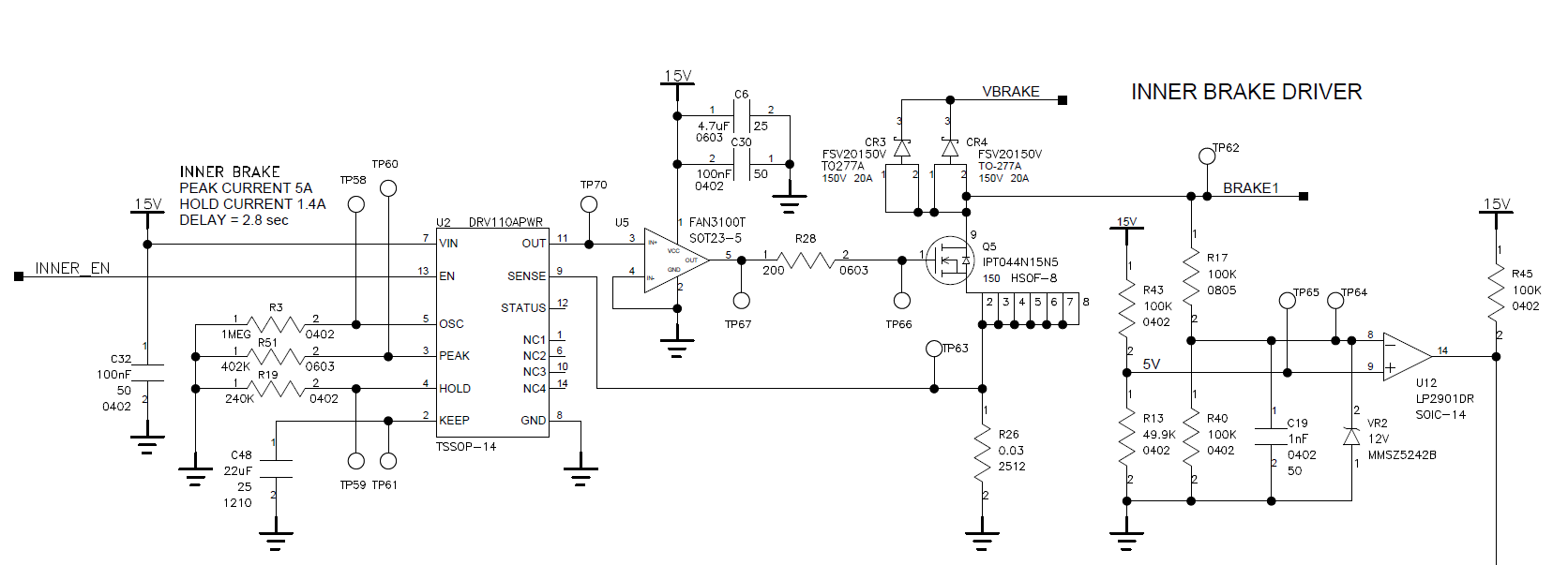
Brake Driver Circuit.pngcurrent--00012.jpgcurrent--00011.jpgon...  

  • HI David, 
    Sorry for late reply. Please let me review it and get back to you by today. 

    Regards

    Mojtaba

  • Hi David, 

    Thank you for the information. 

    I'm driving a brake module which acts much like a solenoid...  The circuit operates from 24VDC to 80VDC but the DRV110 Vin is provided by a 15V regulator...  The circuits works as expected until the voltage is between 57V and 80V...  At that voltage the DRV110 becomes unstable and appears to be ringing...  I've attached the waveform for 56V and the one at 57V for comparison...  Note the green trace is current at the brake, the yellow is the voltage at the current sensing resistor...   The current is upside down.

    From schematic, Ipeak: 5A, Ihold: 1.4A, fPWM: 4kHz, keep: 2.2 sec

    1- Could you please clarify which test is at 56V and whihc one at 57V? 

    2- How is the current measured? it seems that the current prob direction is toward supply not to the load.

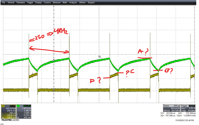
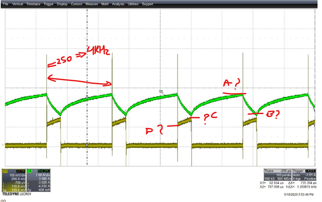
    3- Test A shows higher frequency? the expected frequency is 4kHz. what are the conditions for Test-A? Also the current max, min, and mean is not clear. please measure them.

    4- Did you measure the current during hold or peak condition?

    5- Also can you measure Vout as well along with current and Vsense. 

    6- Vsense looks noisy too. What are the Vsense ( min and max (C&D))?

    Also could you please let me know what are the R and L of the brake motor( solenoid) ?

    Test A                                                                                            Test B


    regards

    Mojtaba

  • Mojtaba,
     
    See my responses below...  Note that I'm a part-time employee with Crown and only work two days a week, Tuesday and Wednesday so if it takes a couple days for me to get back to you, you'll understand why...  
     
    I've added a couple more plots...  These two are both at 48V...  The one with varying duty cycle is at initial turn on at 9A peak and the other is the hold current at 2.4A...  Note that the hold current is a bit high which is another issue we're having...  The hold current output is higher than the resistor set current level...  
    I'm having difficulty attaching additional plots to this reply...  My email bounced a couple times so I'm replying directly on this site...  
     
    Thanks, Dave Beaty

    From: TI E2E support forums <noreply-e2e@mail.ti.com>
    Sent: Thursday, May 21, 2026 13:21
    To: Beaty, Dave <David.Beaty@crown.com>
    Subject: Motor drivers forum : DRV110: DRV110 Instability When Operating Above 56VDC

    External Email: Use caution before clicking links or opening attachments.
    If you are prompted for a password, STOP and report immediately.


    A Message from the TI E2ETm design support forums


    Mojtaba Afshar  replied to  DRV110: DRV110 Instability When Operating Above 56VDC .

    Hi David, 

    Thank you for the information. 

    I'm driving a brake module which acts much like a solenoid...  The circuit operates from 24VDC to 80VDC but the DRV110 Vin is provided by a 15V regulator...  The circuits works as expected until the voltage is between 57V and 80V...  At that voltage the DRV110 becomes unstable and appears to be ringing...  I've attached the waveform for 56V and the one at 57V for comparison...  Note the green trace is current at the brake, the yellow is the voltage at the current sensing resistor...   The current is upside down.

    From schematic, Ipeak: 5A, Ihold: 1.4A, fPWM: 4kHz, keep: 2.2 sec

    1- Could you please clarify which test is at 56V and whihc one at 57V? 

    The circuit operates properly at 56V and below , this is the scope trace that's operating at 4kHz and has a PWM switching waveform with an approx. 20% duty cycle...  Above 56V the DRV110 seems to oscillate with a very small duty cycle and high freq and appears to be ringing...  

    2- How is the current measured? it seems that the current prob direction is toward supply not to the load.

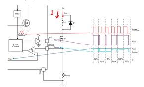
    One side of the brake coil is connected directly to the power supply... The drive circuit is connected to the other side of the brake coil... This design is a low side driver...  The current is measured on the high side of the brake using a current probe...  The pulsed waveform is measured at the current sense resistor...  

    3- Test A shows higher frequency? the expected frequency is 4kHz. what are the conditions for Test-A? Also the current max, min, and mean is not clear. please measure them.

    Sorry, apparently, I didn't capture the ground ref for the current waveform in green...  The current probe was clamped on the wire backwards, so the current waveform is upside down...  But the current measurement is indicated in the green block in the lefthand corner of the pic...

    4- Did you measure the current during hold or peak condition?

    Yes, the current peak is set to 9A and the hold to 2.4A...  I've pics for peak and hold currents below 56V but only hold current above 56V...  I can provide more pics...  

    5- Also can you measure Vout as well along with current and Vsense. 

    Vout is provided by a bench power supply and was set to 48V for the 4kHz traces...  

    6- Vsense looks noisy too. What are the Vsense ( min and max (C&D))?

    The Rsense value is 0.03 ohms...  You can see the Vsense measurement pulses on the scope outputs I sent...  

    Also could you please let me know what are the R and L of the brake motor( solenoid) ?

    I attached a drawing of the brake associated with these waveforms...  The circuit drives two brakes one has the 9A peak the other, not shown, has a 5A peak....  The drawing has most of the electrical information but doesn't list the inductance...  I can measure that for you...

    Test A                                                                                            Test B


    regards

    Mojtaba

  • Hi David, 

    Thank you for your response. 

    I've added a couple more plots...  These two are both at 48V.

    The plots are not shown here. 

    These two are both at 48V...  The one with varying duty cycle is at initial turn on at 9A peak and the other is the hold current at 2.4A

    It is confusing. From schematic, Ipeak: 5A, Ihold: 1.4A, fPWM: 4kHz, keep: 2.2 sec. 

    The 9A and 2.4 A are not matched with the shared data. 

    I'm having difficulty attaching additional plots to this reply...  My email bounced a couple times so I'm replying directly on this site..

    Can you please share the information over email to me. I believe that would be easier to follow up. That would be good to have a meeting to review the information together because the information is not coherent and still confused with the conditions. 

    Please move forward through email. 

    Regards

    Mojtaba

  • Mojtaba, I've had difficulty sending you emails...  I'm getting undeliverable messages when I attempt to send you emails...  Is there another way to contact you...?  

    Regards, Dave

  • Sent you an email. Please check it. 

    Regards

    Mojtaba