This thread has been locked.

If you have a related question, please click the "Ask a related question" button in the top right corner. The newly created question will be automatically linked to this question.

MCT8316Z: MCT8316Z: Motor driver problem IV

Part Number: MCT8316Z

Dear all,

we are again facing a trouble with the "HW" version of the MCT8316Z driver.  Please consider the schema below.

The situation is following: the driver is controlled by discrete 7400-based logic. The driver is set to never sleep, direction signals 0/1 come from the 5V-TTL gates and the PWM signal (either with configured duty cycle 0/25/50/75% or full (100%) as log 1). The PWM signal is purposefully delayed by 1 ms as we noticed (in installment III of these forum posts) that after a direcion change there needs to be a short pause between rising the PWM input. The BLCD motor with three hall sensors (Faulhaber_2250_BX4) is not loaded.

The problem is that after raising the PWM input (pin #39 PWM) to log 1 the motor (in most of the cases) refuses to spin. One can only hear a weak/slight click from the motor. When you help the motor shaft to spin by hand, it starts running just fine. The clicks correspond in time to the FAULT signal being lowered and later on raised (reset) by the pull-up resistor R13.

This means there is some kind of fault. The datasheet gives a list of possible causes for the FAULT signal (p.53-58). This is the "HW" version of the chip so there is no SPI to read out the error register / if there were any in the "HW" version.
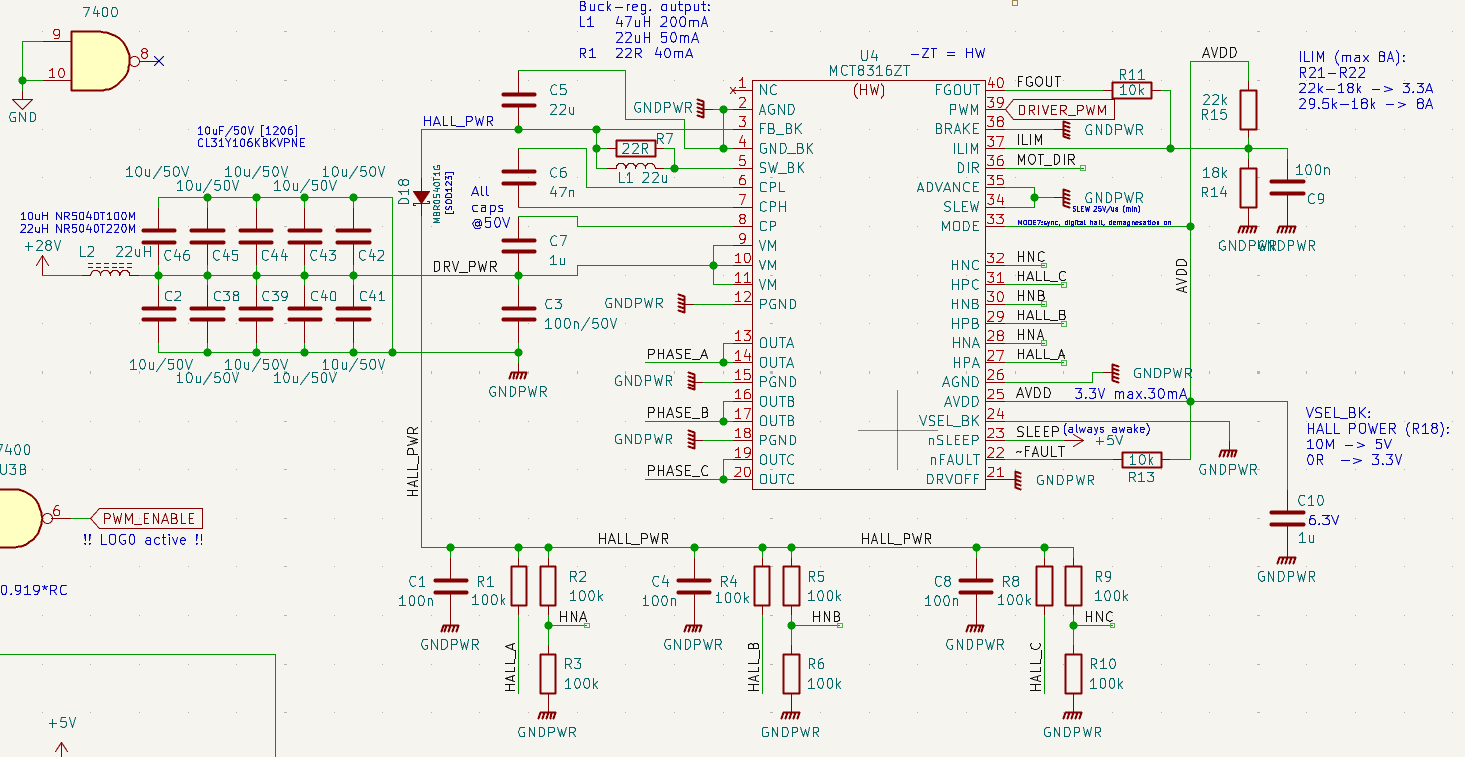
image.png

Addendum regarding the FAULTs:

1. the FAULT signal LOW period takes 500ms while the HIGH remains for exact 1000ms and than falls to FAULT again. This would point to the Motor Lock (MTR_LOCK). However, what I can see with the oscilloscope the signals from the hall sensors seem to be fine - when the hall is low there is approx 400mV while high == 2V.

When the R1, R4 and R8 pull-ups are replaced by 10k, the level high becomes ~3V (essentially the BK voltage) but the behaviour remains equal. 

Removing the R2/R3, R5/R6 and R9/R10 dividers and keeping the HNx floating (as the datasheet suggests) makes not difference. The behaviour is still the same.

Here is a shot when I turn the motor manually, all three hall sensors show the same signal voltages:

This means all HALL sensors work just fine.

After further investigation this seems to be described in section 8.3.16.8 Motor Lock, subsection 83.16.8.2 MTR_LOCK Automatic Retry (based on the behaviour and the times observed).

But what might be the origin of the problem?

Would be grateful for any insights and ideas!


Cheers,

Josef

  • Hi Josef,

    Thanks for providing the detailed schematics for review.
    The schematics look fine, and the HALL/HNX lines should remain floating.
    The issue appears to be a synchronization problem. In the 1 ms pause, does the motor stop completely? After the motor has stopped, wait for the speed to reach zero, then change the direction and issue a speed command by setting PWM log 1 (or whichever duty cycle is appropriate).
    The fault behavior—500 ms low and a detection time of 1,000 ms—matches the hardware device configuration.

    Thanks and best regards,

    Venkatadri S

  • Hello Venkatadri!

    Thank you for reaction. I might have written it in a better way..

    0. The initial state is the motor is stopped. 

    1. The direction is set (left/right).

    2. PWM input is raised to log 1 (100% PWM to avoid any side effect).

    3. The motor is expected to spin but in most of the cased (9.5 out of 10) it does not. The driver demonstrates the behaviour described in the section 8.3.16.8.2 motor lock with automatic retry. Only after I touch the shaft of the motor (move it a little) it starts spininng.

    After I removed the HNx resistors (they are now floating) and it behaves the same.

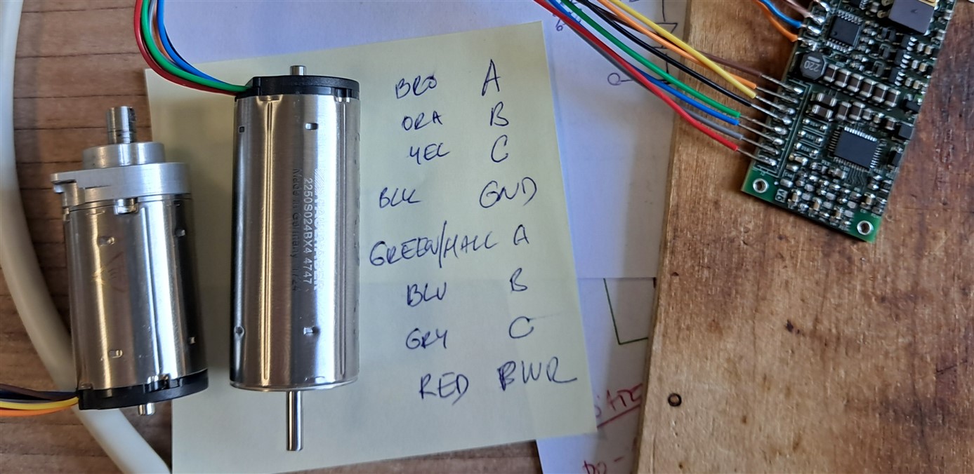
    The situation on the desk looks like this (the motor is not loaded, can spin freely):

    Cheers,

    Josef

  • Hi ,

    This is unusual behavior; it is similar to starting the motor from zero speed. What is the motor’s behavior? Can you enable the brake, change direction, and then release the brake? Can you verify this? Also, can you confirm whether this behavior is observed with the evaluation PCB?

    Thanks and best regards,

    Venkatadri S

  • Hello,

    - the brake is tied to GND on the pcb so it is never active. Cannot be activated. It used to be employed by the TTL logic but as caused unwanted mechanical stress in the drive it has been deactivated this way.

    - I don't have the eval board, however, with other boards and driver the motor works just fine.

    - This is the actual layout surrounding the driver:

    At the bottom is the connector towards the motor, D14-D16 are not populated, neither are the resistor dividers on the right (as mentioned earlier).

    There has not been any change from previous board version in this section and it works there. Might it be a malfunctioning driver IC? Or some other problem?

    Cheers,

    Josef

  • Hi Josef,

    Let me review this again and get back to you.

    Thanks and best regards,

    Venkatadri S

  • An update: a new, slightly larger motor has just arrived, nonetheless, the behavior is till the same Expressionless

    Additionally, I have discovered this post [https://e2e.ti.com/support/motor-drivers-group/motor-drivers/f/motor-drivers-forum/1102147/mct8316z-motor-lock-error-detected-everytime] from Antony Lodi who suggests the "hall inputs the HNx pins must be biased to AVDD/2 to set the comparator threshold to determine what a logic high is and what a logic low is for the hall inputs. This can be set with a voltage divider. If the HNx pins are not set to AVDD/2, the hall comparator will not be able to detect what is a logic high and what is a logic low. ". That is also why we also had the 100k-100k divider on the HNx pins.

    Have changed the pull-ups R1, R4, R8 to 3k3 and repopulated the 100k-dividers with no effect. It still does the same with or without these dividers.

    Currently the voltages on the HALL sensors are:

    - circa 80mV (due to noise) when LOW,

    - 3.35V when HIGH.

    - HALL power (driver's buck output) at 3.47V (with ~ 500mV of noise)

  • All right, folks, after a week we have resolution of this peculiar problem!

    The trouble was in the max current limitation (R14 + R15) where those two damn resistors were swapped on all populated PCBs. This limited the current to some little tiny value which resulted into MOTOR LOCK fault. Just that!

    Or actually, this was result of the OVERCURRENT protection (section 8.3.16.3) which on the HW version is now way to tell while the timing of the FAULT signal is pointing the way towards MOTOR LOCK fault.

    Done. Works (for) now! Nice! :)

    Dismissed! B-)