DRV8256EEVM: Failed to control DC Motor with DRV8256EEVM EVK

Part Number: DRV8256EEVM

Hi Team,

Posting on behalf of our customer.

I will share this post with our customer so he can reply when needed.

I am currently testing a motor with the DRV8256EEVM and would appreciate your support.

My motor specifications are 24 V / 60 W.

During testing, I configured the setup as follows:

  • Power supply: 20 V with a 3 A current limit
  • Vref set 3V3.
  • Connected the outputs in parallel by tying OUT1 of J4 and J5 together, and OUT2 of J4 and J5 together, then connected them to the motor.
  • Used the DRV8256EVM GUI from the TI website to control the board.

The issue I observed is:

  • When EN = 50% and PH = 100%, the motor does not rotate.
  • The power supply indicates a current of approximately 0.23 A. Voltage between OUT1 and OUT2 is 1.3V, and the motor only produces a humming noise as if it cannot start.
  • The motor only runs when EN = 100% and PH = 0% or 100%. I would like to control the motor speed while maintaining both CW and CCW operation.

Could you please help troubleshoot this issue and confirm whether the DRV8256EVM supports motor speed control by applying a PWM signal to the EN pin?

Additionally, I have attached my schematic. I would like to isolate the control signals between the MCU and the motor driver, so I modified the nFAULT signal circuitry accordingly.
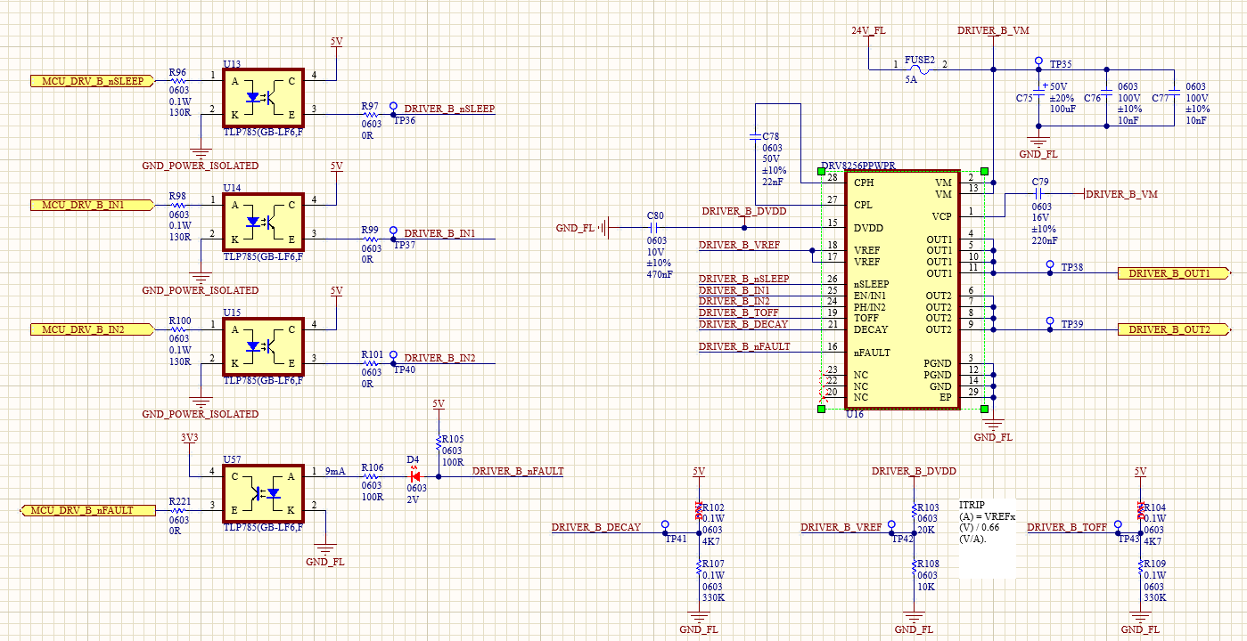
image (6).png

Could you please review the schematic and let me know if there are any issues with my implementation?

I look forward to your response.

Thank you for your time and support.

Regards,

Danilo

  • Hi Danilo,

    Thank you for the questions. Please give us a little more time to review on it and get back to you early next week. Thank you.

    Best,

    Yuzhou

  • Hi Danilo,

    Thank you for your questions again.

    When you let EN=50% and PH=100%, the output voltage applied on the motor will be a positive voltage on a half period and a negative voltage on the rest of the period (or part of the rest of the period) due to the inductive current of the motor flow through the body diode of the FETs. That was the reason why you observed a very small average voltage applied to the motor with very small motor current. And with this small current, the motor wasn't able to start.

    When you let EN=100% and PH=0% or 100%, the voltage applied to the motor will be either 100% positive voltage or 100% negative voltage. And the motor could run in these conditions.

    If you would like to have speed regulation, you are able to modulate the percentage of EN to control the speed either by implementing the external close loop control with encoder or utilizing internal current regulation for speed regulation.

    For the schematic, it looks in a good shape from device perspective. If you would like to isolate the control signals between the MCU and the motor driver, please also check that if you also isolated the power supply of the MCU and the motor drive. Thank you.

    Best,

    Yuzhou