This thread has been locked.

If you have a related question, please click the "Ask a related question" button in the top right corner. The newly created question will be automatically linked to this question.

DRV8841 Output A and B different?

Other Parts Discussed in Thread: DRV8841

Hi,

I'm using the DRV8841 H-Bridge to actuate a DC-latching solenoid used to switch a valve(the valve is not attached atm). It switches 12V over the solenoid in one direction to turn it on, and 12V in the other direction to turn it off. A microcontroller controls the AINx and BINx. ISENB and ISENA as well as AI0/1 and BI0/1 are tied to ground since I'm not using them. DECAY is left open.

My problem is that switching the valve on port A is no problem in either direction. Switching the valve on port B in either direction causes the nFAULT pin to pull low. Since it doesn't reset until I use nRESET or reset the power, I assume this signalizes an overcurrent fault. I do not understand why there would be a fault on port B and not port A when using the exact same solenoid, and everything else is symmetric as well. Also, the solenoid has a short current spike of 1.2A or less, so it should not cause an overcurrent in any case (3A overcurrent trip level). I assume the H-Bridge is not damaged since I tried it with 2 different ones, and I get the same error in either case. When the solenoid is not attached, there is no fault. I also tried putting a 4.7Ohm resistor in series, which would technically limit the current to a max of 2.5A, but it has the same problem.

Any ideas what I'm doing wrong? Or is there a different overcurrent setting for the two ports somehow?

Thanks for the help,

Samuel Boegli

  • Hi Samuel,

    This is very odd indeed. Are you using one of our EVM's or your own board? Any chance there is a short to GND or VM on the H Bridge B outputs? What you describe sounds like an OCP event so it seems the system is seeing more than OCP current for a few microseconds which is construed as an OCP event.

    I imagine you tried to drive on H Bridge B the solenoid that works on H Bridge A, right? If not, can you swap around the solenoids in order to make sure the problem is with H bridge B and not the actual load?

    If it is your own board design, can you post the schematic so we can see how you are wiring the system? Thanks!

    Best regards,

    Jose Quinones

  • Hi Jose,

    Yes, I used the same solenoid to test it. I don't measure a short to either GND or VM, nor can I see one.

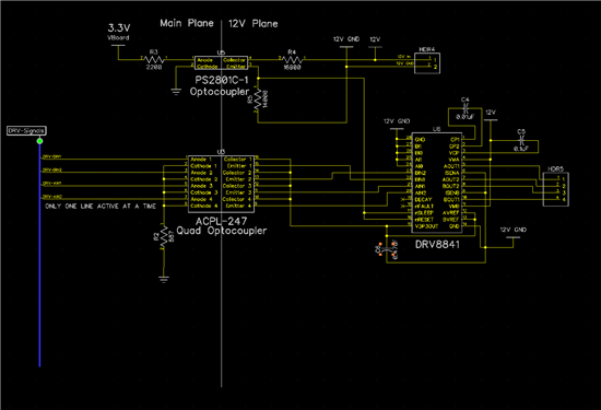
    I attached a picture of the circuit. I am using optocouplers to separate the ground planes because I don't want the current from the solenoid to interfere with any other circuits on the board. An external 12V source powers the DRV and Solenoid. Since the board is designed to be off most of the time, but the 12V source is available at all times, I am using one optocoupler to activate the DRV when 3.3V are on the board. The voltage at nSLEEP and nRESET is around 5.1V. The quad-optocoupler is used to transfer the signal from the microcontroller to the DRV. I believe using the V3P3OUT pin to drive the BIN and AIN pins is ok since the source has a maximum draw of 1mA, and the input pins a max draw of 100uA. Would damaging the V3P3OUT possibly cause a problem like this?

    The Thermal Pad is attached to the 12V GND Copper Plane. The rest is pretty much according to the datasheet.

    Thanks for the help,

    Samuel