This thread has been locked.

If you have a related question, please click the "Ask a related question" button in the top right corner. The newly created question will be automatically linked to this question.

Stepper Motor Driving Issue DRV8821

Other Parts Discussed in Thread: DRV8821, DRV8821EVM

Hi All,

Good Day.

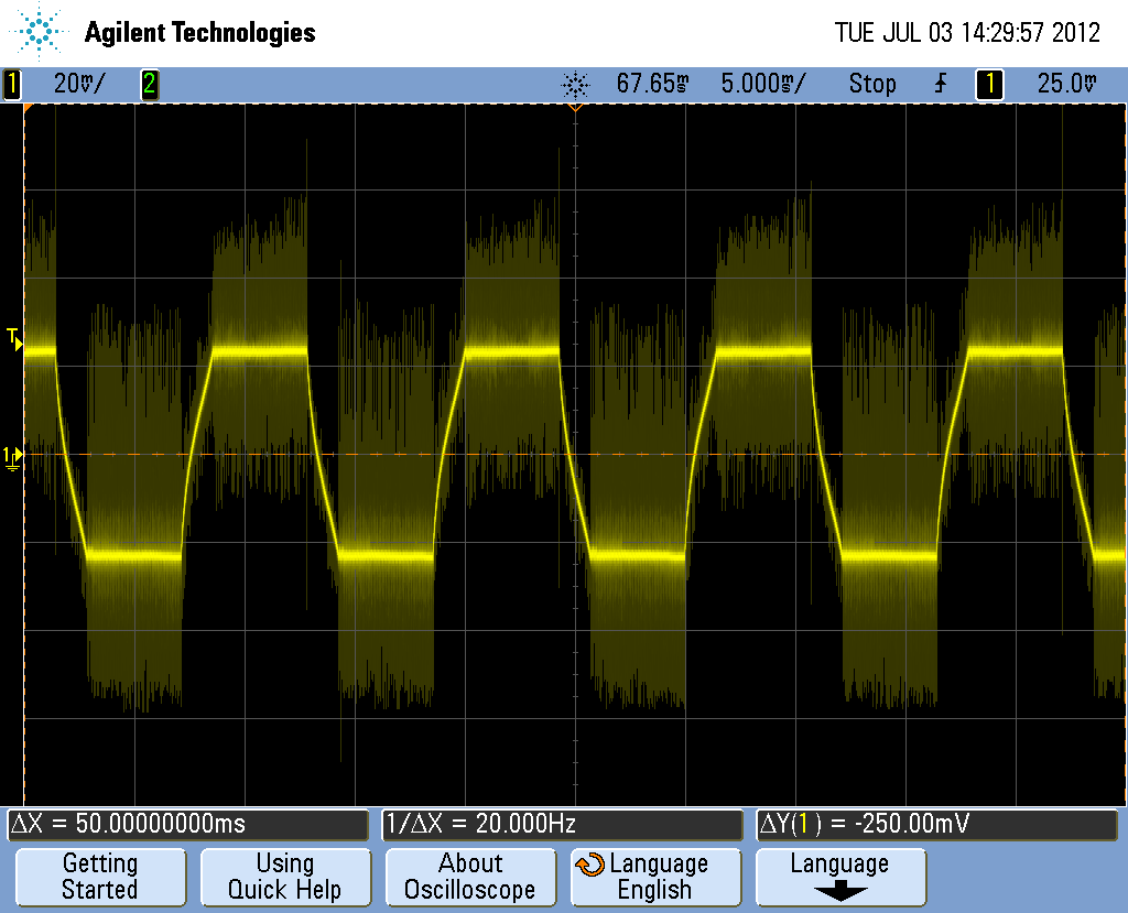
We designed a circuit which we can run two Double stack stepper motors using DRV8821. Without current limit for short duration we have not seen any noise on the current waveform. After that we chopped our circuit to 1.32A by adding 0.5Ohm resistor. But now my current waveform is having much high frequency noice. Can anyone suggest why it so??How to reduce it ?? Kindly help me out to get pure current waveform.

Regards,

Samson 

  • Hi Samson,

    Can you share a capture of how the current look on both cases? With the description I can only guess in one case you are driving the stepper into saturation, in which case there is no current regulation taking place (no noise), and in the other case you are using current chopping, in which case there will always be some audible noise as being generated by the current regulation.

    Best regards,

    Jose Quinones

  • Hi Jose,

    Thanks for your reply.

    Yes,when we chopped the current to 1.32A or 1A we are getting much noise. But, one thing i would like to discuss. We are using Neocene motors. They have sent the tested reports of motors with LB1845 driver  with current chopping 1A. I was really wonder thier current waveform is pure without any noise. Kindly suggest me why it was like this?? We are 100% sure our TI product is much better than that.  Kindly help me out from if any board design change require, or there is any measurement error from our side. I will post our current waveforms as early as possible. We are using this driver from long time. But we have not seen such deeply before. Since we require much torque we decided to check all these things. 

    Hope you can help me.

    Regards,

    Samson 

  • This is my Current waveform. I would like to have much reduced noise waveform. Kindly suggest me how to get??

    Regards,

    Samson

  • Hi Samson,

    Could you try slow decay mode? If the noise is real, it may be caused by fast decay into a low inductance motor. You could also try to see if the noise diminishes by reducing the input voltage. I would also try and zooming into the noise to see whether you see the typical current up/down swing of a current chopper.

    The noise seems suspicious, thouhg, as I can see it on the current increase (phase change) as well. This noise can not be caused by the chopper as there is no chopping on that H Bridge during that portion of the cycle. It may be coupling from the other phase (which is definitely chopping as both phases are 90 degrees out of phase), so you could also have some layout issues. For that we would need to look at the layout. Feel free to send the Gerber files to my email address and I'll take a look.

    Best regards,

    Jose Quinones

  • Dear Jose,

    Thanks for your valuable reply.

    We tried with Slow decay also. But we felt there is no difference btw both modes. As per my company norms i can't send the gerber files to anyone. It is against the company rules..Kindly suggest me what should be the track size if we are driving the motor at 1.32A.. At initial  we tried with 12V,Even though we got the same waveform. To improve the torque we started to check with 24V. One thing i would like to ask you..How much capacitance i need to Keep at VCP pin and Vm pins when my input is 24V. I need exact values..What type of capacitors need to use?? Will these effect my output?? 


    Regards,

    Samson

  • Hi Samson,

    I do not think this is about track size, but about component placing. I recommend you take a look at our DRV8821EVM's schematic and Gerber files to see how we implemented the device around a microcontroller. We know this implementation works without the noise you are observing so this should work as a good reference. All I can say is that track size should be as thick as possible. I like starting off with 15 thousands of an inch and then increasing to 50 as soon as possible.

    The caps you should use are detailed on the device's datasheet. The  VCP caps are ceramic and on VM to GND you should use something like a 100 uf electrolytic cap and a 0.1 uf ceramic cap in parallel. The selection of the VM caps is rather flexible. For example, you can use anywhere in between 100 uf to 220 uf and you should not see a lot of change on the outputs. The VM cap is meant to eliminate ripple on the VM line possibly caused by fast decay dumping current back into the supply. This is the application specific portion so I just cannot tell you which cap to use. You will need to experiment with your own application constraints and use the cap that best fit your needs. But mostly any cap should do fine.

    I didn't mention this before, but It is also possible the noise you are observing is an artifact of the measuring equipment. This is of course just a guess based on the picture you posted earlier. On this picture I see the conventional current ripple which is expected of any current chopper topology driver. The faint ripple, however, looks very suspicious and I wonder whether it is real or not. I would zoom into the current chopping cycle to validate what is going on with the phases. I would also look at the current and the outputs at the same time. It helps to figure out what may be going on.

    Hope the info helps. Best regards,

    Jose Quinones