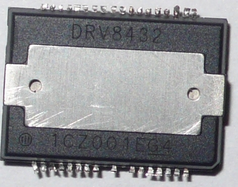
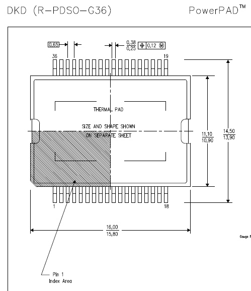
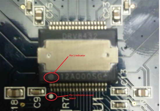
Having big problems getting my DRV8432 prototype up and running. I am driving a 1.8 degree/step stepper motor, Anaheim Automation PN 34Y004S-LW8 with a simple full-step algorithm, and PWMing the drive pins to set operating current. I have already done a successful design w the DRV8825, but my client now wants faster/more torque. First question is pretty fundamental: WHERE IS PIN ONE? The spec document shows that the notched corner marks pin 1, but I found a TI user forum entry that suggests that the corner marked on top with a circle w three lines through it is actually Pin 1. So which is true? I went with the circle on my first build, and the parts seem to work with no load on them, I can see PWM output on the OUT A,B,C,D pins, but the instant I hook up a stepper motor to the outputs the DRV8432 dies. The 12V lines (GVDD) draw around 30mA before this, then after the part is damaged, GVDD current draw is over 250 mA. Measured resistance ground to GVDD on the dead parts is about 90 ohms static measurement, so the DRV8432 has apparently shorted out internally.
The documentation shows the notch on the part marking PIN 1 but NOT at the corner the notch actually appears on the part! What's correct here?


