This thread has been locked.

If you have a related question, please click the "Ask a related question" button in the top right corner. The newly created question will be automatically linked to this question.

Some clarification on the output of the DRV2665

Other Parts Discussed in Thread: DRV2665, DRV2603

Hi guys,

I have some piezo actuators I need to drive at 60V, and as the main page of the the IC as quoted here says:

The DRV2665 is a piezo haptic driver with integrated 105 V boost switch

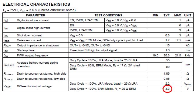
However, after reading the datasheet as emailed to me, I read that the output ranges only up to 3.3V? What does the "105V boost" mean here? Can this IC be used to drive the piezo actuator as mentioned? 

Thank you very much for your time.

A.Halim Poh

  • Hello A. Halim,

    I think you may be misreading it?  Could you point us to where you are seeing this information?

    On the posted Datasheet in the product folder the 3-5.5V supply range is on the input for VDD, the output swing out of  OUT+ and OUT- is where the +/-105 Volts comes out thus giving a 210VPP range with a breakdown as follows:

    High Voltage Piezo-Haptic Driver
    – Drives up to 100 nF at 200 VPP and 300 Hz
    – Drives up to 150 nF at 150 VPP and 300 Hz
    – Drives up to 330 nF at 100 VPP and 300 Hz
    – Drives up to 680 nF at 50 VPP and 300 Hz
    – Differential Output

    So given you are driving 60VPP you should be good for up to 680nF actuators.

    Let us know if this doesn't address your answer.

    --Eric Siegel

  • Hi Eric,

    Thanks a lot for your reply. So this means that the output voltage is dependent on the capacitance of the piezo actuator, am I correct? I obtained the info from the datasheet as attached, but it is for DRV2603 though:

    My power electronics theory is a bit rusty, you see. The capacitance of the actuator is 1150nF though. So how do I go around this? Do I add capacitance in series to tune the capacitance down to 330nF? 

    Thanks a lot for your input.

  • Ah, that's is the problem, the DRV2603 is not a piezo actuator driver, that is designed for ERM and LRAs (typical DC motor-esque applications). If you need to drive a piezo actuator please refer to our piezo driver selection page. And yes the size of the actuator's capacitance dictates how well the driver can drive it, the previous post gave you some performance points of our drivers.

    To answer your circuits question yes, capacitors in series reduce via ((1/C1) + (1/C2) = (1/Ctot)), where as capacitors in parallel sum up (C1 + C2 = Ctot).

    That being said we aren't sure if that trick works for actuators and allowing them to maintain their vibration strength and operating conditions.  Let us know how it goes?

  • Hi Eric,

    My bad, I referred to the wrong datasheet. I must have clicked wrongly upon the request for it. 

    On the other hand, if there are series capacitance with the piezo, wouldn't there be a voltage drop across the extra capacitance, making the voltage drop across the piezo terminals itself lower? Whoa I really need to study my fundamentals back. Sorry for my mediocrity here.

  • Hi Eric, 

    What is your opinion? I'm not sure if the series capacitance enables the piezo to be driven at higher voltages, since there'll be a voltage division between the extra capacitor. The piezo actuator hasn't arrived yet, so I could use some extra pointers before actually experimenting.

  • A. H.

    Honestly I'd start with the actuator and driver with nothing in between and see how it goes first, and then slowly start adding more capacitance in series.  You are venturing into new territory for us as we recommend that you buy an actuator in the given spec range we've listed in the datasheet, but if yo udo the calculations right you should know how much Cap to add in series.

    Best of luck and keep us posted on how it goes!

    --Eric