This thread has been locked.

If you have a related question, please click the "Ask a related question" button in the top right corner. The newly created question will be automatically linked to this question.

DRV8824 vibrating, not turning

Other Parts Discussed in Thread: DRV8824

Hello fellow coengineers,

I am trying to get two stepper motors to run. In order to do so, I set up a circuit including DRV8824s which are being controlled by a microcontroller.

Once I send a given amount of pulses on the STEP line, the motor starts vibrating but does not turn. Hereby the length of the vibration is propotional to the amount of pulses sent on the STEP line, which makes me guess that it's a problem related to the commutation of the windings and/or power through them (and it's not just some random vibration).

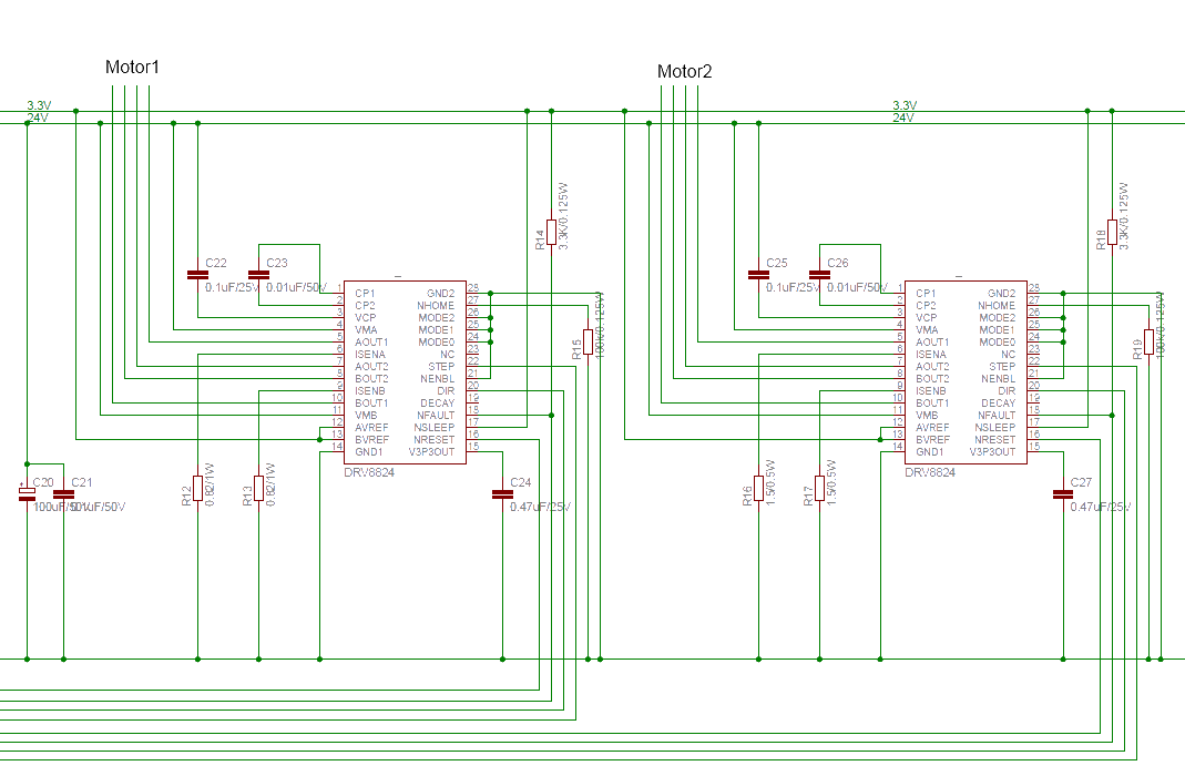
I have attached an excerpt of my board's schematic. The maximum current through the motor windings should be 0,85 and 0,45A, hence the 0,82 and 1,5Ohm on Isense.

The fact that both steppers act in the exact same manner makes me think that the problem does not lie in the motor itself, but rather in the controlling board. But I just can't figure out what might be wrong, therefore some help would be greatly appreciated.

  • I have figured that the Problem might be the current limiting. I have been measuring the current while driving the motors. The motor that can be driven with up to 0,85A just draws 0,12A, the one that should be drawing 0,45A is drawing 0,16A.

    I figure I have messed up the current limiting resistors. If in the motor's datasheet a current limit of 0,85A/Winding is stated, should the current limit in the DRV8824 be set to 0,85A or 1,7A (since it has two windings) ?

  • hi, lennart,

    the current limit in the datasheet is for each winding, and if you want to limit the current in 0.85A, just set to 0.85A, not 1.7A. and the PIN nHOME should be pullup ,not pulldown, and by the way  ,i just want to make sure that:

    1. the PIN  nRESET is pull up to HIGH;

    2. you connect the stepper motor windings in right order;

  • Hi Brady,

    thank you for the effort.

    I actually managed to get it to turn now. The problem were indeed the current sensing/limiting resistors, I replaced them with ones half the size and now the 0,45A motor draws up to 300mA and actually turns.

    The next problem is that it it just turns up to a certain speed, which is not high enough for my application. As the current is still not hitting the motor's limit, I wonder if further reducing the resistors would do the trick.

    But as this is quite against the driver's datasheet, I wonder what might be wrong. I measured Vref, which indeed is at 3,3V. Therefore I=V/5*R = 3,3V/5*0,82 = 0,8A . Why is it limiting at 300 mA?

    Edit: I don't need the Home output, so I pulled it down to ground.

  • Hi, lennart,

     it may be the speed you give the stepper motor that cause this problem, because of the Characteristic of stepper motor ,it can not start up if you give it a relatively  high speed, it should start up from a slow speed and accelate to the speed you want. you can try to slow down the start up speed,and see  if any change.


    by the way ,there is a document about the accelerate and deccelerate of steppet motor, you may have a look :

    http://www.ti.com/general/docs/lit/getliterature.tsp?baseLiteratureNumber=slyt482

  • Hi Brady,

    well I'm doing just that. Starting with 90 Steps/s and then going up with about 50 Steps/s². This works fine up to 1100 Steps/s, then it stalls.

    I need to turn the whole thing up until about  7000 Steps/s.

  • Hi,lennart,

                 are you sure your stepper motor can run in the speed up to 7000 step/s in full step mode ?  or what you say 7000 step/s  is in micro-step mode?

                 if your stepper motor stall at 1100 step/s , you may further reduce the sensing resistance to see if any change, just keep the max current below 1.6A and that will be OK.

  • Hi again,

    According to the it's Datasheet, the motor should be able to manage that speed. 

    I have a question related to the hold current: How is it limited in the DRV8824 ? Since it seems to be somehow related to RIsense; Is it a certain percentage of Imax

  • Ups, ignore that. I was measuring on the wrong line.

    I do have 0,44A on the motor's leads when the motor is holding. Once it starts rotating, the current falls with the motor's speed. Until at 1100 Steps/s, when the current falls below 390mA and the motor stalls.

    As I understand chopper drivers, this current decay should not be (since that's the point of the chopper drive, isn't it ? ). What may be the issue here ?

    The Voltage I am applying is 12 times the motors rated voltage, so I don't think this could be a problem (especially not at these low speeds).

    Anyway, thank you for your support and fast answers.

  • Hi, lennart,

                 as the speed go up, the current fall to 0.39mA , it is a normal phenomenon, because the back EMF increase.

                 stepper motor is not fit for high speed application, i think you may check  your stepper motor specifications,  i supposed it can not  run up to 7000 step/s(in full step).

    now the stepper motor run up to 1100step/s and stall,  if you want to   run it faster   you can increase the voltage  to see if any change

  • Hi.

    I am very disappointed by the level of TI's help.

    I know that the back-emf increases, but this is exactly why I am using a chopper control, and not a pure Voltage driven control. Countering the back-emf with a much higher voltage in order to maintain the required current through the windings is the whole point of chopping, isn't it ? And I don't think I should be the one explaining TI's expert on motor drivers how a chopper control works and what it's for.

    Plus, in the motor's datasheet is stated that the back-emf consists in 2,4 V/kStep/s. Turning with 1kStep/s would therefore have 2,4V of back-emf. Having 24V available, the driver should easily be able to counter that back-emf and maintain the required current. This might become a problem at higher speeds, but not here.

    And once again: The motor is capable of driving that speed. Without any load the motor should even be able to turn until over 8kSteps/s (20.000 rpm).

    Yes, I know that increasing the voltage may get it to turn. But firstly I won't get to have a higher voltage in my application (except implementing a boost converter, which makes the entire thing more expensive and prone to error), and secondly I expect a stepper motor to be able to turn with over 2500rpm when the applied voltage is 12 times the rated voltage. Your help is just not helping.

  • Hi Lennart,

    In this case I'm currently not sure what to make of your situation since we don't have much more information other than it stalls at 1100steps/s and that the current regulation seems to be bad. Your setup seems to have accounted for most of the issues our customers normally experience when trying to get the motor to start. It seems from your description that the motor rotor starts up fine but as the steps/second increases the rotor loses synchronization with the commutation of the winding which causes it to slip. Once this happens the rotor loses inertia and will never be able to catch up to the commutation speed of the outputs (as you probably already know). Have you ruled out the possibility of mid-band resonance causing the motor to stall?

    How are you measuring the current through your motor? Is it a multimeter in series or do you have a current probe on an oscilloscope? If you're just using a multimeter, you will only see an average current and not the peak current that the motor is drawing. If the latter, do you have screenshots of the current through the motor winding when it stalls? Posting these would be very helpful in understanding what is happening in the driver. Do you ever witness the nFAULT signal go low?

    I would also care to see the link to the datasheet of the motor. I believe it can go as fast as you say but I would like to see the speed/torque characteristic. What is your load?

    Based on your schematic everything seems to be in order. Do you have the circuit implemented on a PCB or breadboard style? The length of the trace between the isense pin and the current sense resistor does matter in application. Since the sense resistor is in series with the output FETs a long trace will cause additional voltage drop in the line, which may cause the current regulation circuit to trip early. If it is not already I suggest moving this resistor as close as possible to the sense pin.

    Have you considered going into a microstepping mode rather than full-step? It's possible that increasing to half-step  (mode 001) instead of full-step would help the rotor maintain synchronization with the commutation of the motor windings. You would have to issue step pulses twice as fast to achieve the desired rpm. As a side note, in full-step mode the device auto-regulates the output current to 71% of the full scale chopping current so you will not get the maximum drive strength out of the device.

    I would also suggest putting the device into fast decay by pulling the decay pin high - this allows the current switch orientation in the windings more quickly. Doing this will however increase your torque ripple and audible noise of the motor.

    Even if this doesn't solve the problem completely, please let me know the results of the above experiments and we can try to help deduce where the problem may lie.

    Best regards,
    Casey

  • Hi Casey,

    thank you very much!

    I know I might have sounded rude before and I would like to apologize for that, but the answers I was becoming were rather trivial and just not up to my expectations.

    I guess the motor really is stalling due to some kind of resonances. I'll implement microstepping to reduce this.

    I am measuring the current with a multimeter in series with a motorwinding so I guess I am in fact measuring the average current.

    Is there a way of calculating the average current through the maximum current limit? What I mean is: If my motor has a rated current of 450mA, I would like it to constantly draw 450mA to drive. Short current peaks exceeding the rated current should not be damaging the motor and are therefore acceptable (as long as they stay short). Having that in mind, I would rather be setting Iavg than Imax. Is there a known correlation between Iavg to Imax, some kind of Iavg / Imax  coeficcient? If, say,  Iavg/Imax = 0,6; the average current through the winding in full step would be Iavg=Imax*0,6*0,71=Imax*0,43. If the current limiter is then set to the motor's rated current (in this case 450mA), the average driving current would be only around 43% of the rated current (in this case 191mA), in which case the motor would obviously not reach the torque stated in the datasheet. If the  Iavg / Imax coeficcient is known, Iavg could be appropietly set through RIsense .

    Apart from that, as the controller only supplies 71% in full step mode, is it wise to take this into account when dimensioning RIsense (by making it 29% smaller), or is this done to protect the motor's windings?

    No, nFault has never yet gone low, which is quite astonishing because the driver does get quite hot. TI has done a pretty good job there. (and I have not while layouting...)

    The motor is the following: http://www.faulhaber.com/uploadpk/EN_AM1524_PCS.pdf. Except for a 1:66 gear there is yet no load on the motor, and ultimately it will not turn much more than two ball bearings.

    The circuit is implemented on a PCB. The traces are in fact a little long (about 4cm), and this may cause RIsense to actually be bigger than only the resistor, good hint, thank you. I will take this into account when designing the next prototype.

    Half/quarterstepping is also an option which I'll implement to reduce noise and resonance issues. Additionally, I will reduce the motor's gear in order to reduce the required stepping speed and all the electronical challenges this comes with, the next gear will be 1:20, so the maximum stepping rate will fall from 7000Steps/s to 2000Steps/s.

    I am not really eager to set fast decay, since it does have its annoying disadvantages. And yet, I don't really posess sufficient experience with steppers to be able to say whether this is definetly going to be necessary or not. What is your suggestion here ? Do you think that there will be no way around ? I guess at 7kSteps/s it would have been absolutely necessary, but is it also at 2kSteps/s ?

    I'd like to thoroughly thank you once again for your time and very helpful hints.

    Regards,

    Lennart


  • Hi Lennart,

    You're very welcome! I can understand the frustration as you topic has been open quite a while - hopefully we can get this sorted out soon and get your motor working properly. 

    To answer your first question, first let me say that my statement that the multimeter will see the average current through the winding is a bit misleading. The value that is seen by the multimeter is the RMS (root-mean square, or quadratic mean) of the current through the winding. This is the effective current your motor winding will see and for sine waves is given by: Irms = Ipeak / Sqrt(2).

    This behavior offers a good explanation to your post on Jan 25 where you have a resistance of 0,82 ohms but the output is limiting to 300mA instead of 800mA. Using the above equation

    Irms = 0,8/Sqrt(2) = 565mA.

    Then, taking into account the 70% (my mistake on saying 71% before) current regulation in full-step mode, 0,565*0,7 = 395mA. This expected result is still a little higher than what you are actually measuring - however, if we speculate that the length of the trace on the ISENSE pin adds another ~260mOhms to the total resistance of the sense resistor, this would account for the 95mA difference between expected and actual measurement.

    To properly size the resistor then, you'll want to start off with Irms = rated motor current. This will allow you to calculate what the peak current will be - this Ipeak will be the current you want to size your resistor for.

    For your second question, the 70% current regulation is indeed intended to protect the motor windings as well as help with current slew rates through the winding in full-step mode. It is not recommended to reduce the sense resistor by 30% to take this into account, but if more current is necessary then it should not hurt. I would say to just take care and make sure that at this level you're not exceeding the current ratings of the motor and that the chassis doesn't get too hot.

    Speaking of heat - you mentioned this is a PCB design. As long as you're not hitting a fault condition the fact that the device heats up quite nicely should not be a problem. However, If you're concerned about the device getting too hot or run into this problem in the future, you may consult this document about PowerPAD layouts which should reduce the running temperature of the device: 

    http://www.ti.com/lit/an/sloa120/sloa120.pdf

    Finally, I would also agree not to use fast decay unless it's necessary. Doing as you have done in your schematic and using mixed decay mode is generally a pretty safe and reliable mode of operation. At 2kSteps/s I do not believe it will be necessary to enter fast decay, but if the other changes don't manage to get your motor spinning correctly it's definitely worth a shot just to see what will happen. Perhaps add a 3-pin header to your design where you can either pull the pin high, low, or leave it open using shunt jumpers to give yourself some more flexibility in future builds. This could also be done on the mode pins if you would like to experiment with different degrees of microstepping but not necessarily commit to one mode or the other. 

    Hope this info helps! Let me know if you get the motor running - if not I'll be glad to help you troubleshoot further.

    Best regards,
    Casey