Hello,
I’am testing current capability of the DRV8332 driver. I use a current step of 10A, where I measure how long the motor driver is capable of handling peak current before going into a limiting mode.
In the test the motor stands still, so only 2 FETs conduct during on-time, where I use synchronous rectification for the other 2 FETs. I have a small duty period of only 10%, so there are only 2 FETs conducting most of the time (90% of the period).
This of course, gives a worse thermal resistance compared to a commutating motor, where the power is dissipated between all the transistors.
From the datasheet, I can see the thermal resistance of junction-case is rated to 0.9 K/W. I can see there is an assumption that all FETs are conducting, which is the case for average power of a commutating motor. (perhaps the j-c thermal resistance should be specified more clearer in the datasheet?)Refer to this thread:
http://e2e.ti.com/support/applications/motor_drivers/f/38/t/162239.aspx
Now in my case I have only two FETS conducting, this will give me an approximation of a j-c thermal resistance of 3 K/W (6 K/W for one FET).
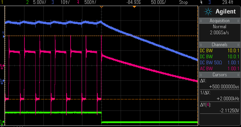
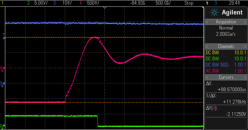
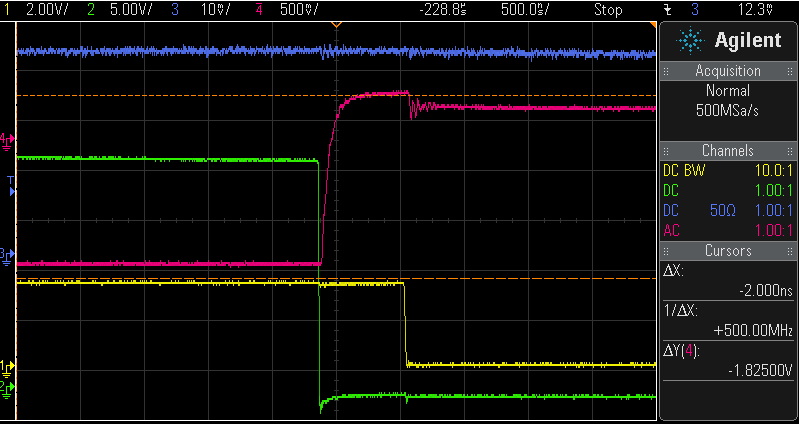
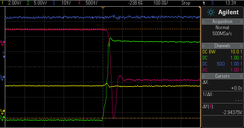
In my case the DRV8332 can handle a 10A current for period of around 7ms, before going in Cycle-by-Cycle current limiting mode. Is this normal for this motor driver? I would expect a thermal shut-down, but I receive a FAULT instead. I use a 19.6k resistor for oc_adj, which will give a higer peak current limiting value.
Thank you in advance,
Pavel