This thread has been locked.

If you have a related question, please click the "Ask a related question" button in the top right corner. The newly created question will be automatically linked to this question.

DRV8844 Current Sense

Other Parts Discussed in Thread: DRV8844, DRV8313, DRV8813, TMS320F28069, CONTROLSUITE

Hi,

I'm using a number of DRV8844 chips in my solution and am curious to know if there is any way I can sense motor current.  I am using two outputs of the quad H bridge (a full H) to drive a DC motor.  I have placed a sense resistor on one of the outputs, but thise seems to be producing strange results.  I noticed that there are four connections to ground, presumable 1 per half bridge, can I place my sense resistor between this connection and ground to achieve current sensing?

thanks

  • Hi Luke,

    You might want to consider using the DRV8313 instead.  It's a very similar device, and has built-in current limiting.

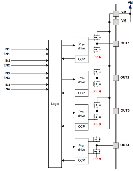
    For the DRV8844, I believe you could put a small sense resistor to ground on Pin 6 VNEG.  I believe this pin is the low-side of OUT1 and OUT2.

    Best regards,
    RE

  • Thanks for the quick response.  Unfortunately, we are commited to using the DRV8844 as majority of the board layout is already done.  Is there any way to confirm the ground pin issue?  

    If I want to sense 1/2 bridge 1, does the sense resistor get connected between pin 6 and ground or pin 5 and the device. Will either / neither work?

    If I want to sense 1/2 bridge 2, does the sense resistor get connected between pin 9 and ground or pin 7 and the device. Will either / neither work?

    If I want to sense 1/2 bridge 3, does the sense resistor get connected between pin 14 and ground or pin 8 and the device. Will either / neither work?

    If I want to sense 1/2 bridge 4, does the sense resistor get connected between pin 28 and ground or pin 10 and the device. Will either / neither work?


    Looking more closely at the block diagram, it seems there are two grounds connected to the output stages of the chip (1 pin / H bridge?), and two ground pins.  Can someone provide clarification?


    Thanks

  • For what it's worth, the DRV8813 has the same package and nearly the same pinout as the DRV8844, so there wouldn't be tremendous layout changes.

    I confirmed with the device designer that this picture is accurate.

    Basically, Pin 6 is the low-side for OUT1 and OUT2, so you should be able to connect a small sense resistor from Pin 6 to GND, and its voltage will indicate the absolute value of the current through OUT1 to OUT2.  Alternatively, you could place a sense resistor in series to OUT1, but its voltage polarity would change with your motor direction.

    Best regards,
    RE

  • Great, that's exactly what I was looking for!

    Thanks.

  • I want to use the DRV8844 instead of a DRV8432. For controlling stepper motors with microstepping. The DRV8844 with 60 V power supply gives ne a little bit more saftey for 48 V powering. For control I use a TMS320F28069 processor. I'm using a triagular (symmetric) PWM. At EPWM counter zero the lower transistors of both halfbridges connected to a fullbrige are closed and the current is circulating in the lower part of the fullbridge. Because each half bridge has its own GND I can measure very easy the motor current at this time. According to the picture the DRV8844 has no individual GND Pin for each half bridge. Therefore I can only measure the current during the on time of the PWM. Is that correct? That is a big disatvantage for a low cost current sensing.

  • Hi Christoph,

    Correct, there is no individual GND pin for each half bridge. From the picture posted above (dated June 11, 2013), each full bridge has its own GND.

    For stepper operation, this is sufficient.

    If configured properly, current can be measured during both on time (positive voltage across the resistor) and fast decay (negative voltage across the resistor). Since current re-circulates through the low side during slow decay, there is no current in the resistor.
  • Hi Rick,

    not if you do in a similar way as in the application note of the DRV8412-C2-KIT in the controlSUITE. In this stepper application there are using two independant PI controllers to control the two stepper phases currents. This is working very good. Especially at the zero crossing point of the currents. With all kind of windowing (hysterese two point control) you have problems in this region.

    Such a control also has its advantage in the stand stil. The constant current you need for a fery precise positioning is much better as with fast decay mode. And if you really need fast decay (positive current and at the falling edge of the sinusodial curve) you will get it because then you are driving the full bridge in the oppsite way (input of PI contoller is negative because you are lagging behind the sinusodial curve). So this chip is not sufficiant for a very precise stepper control. It agree with you that this chip is sufficiant to let a motor turn but not for a very precise positioning (micro stepping in in the range of the 12 Bit ADC converters of standard C2000 family) together with an optical ruler.

    Everything is working perfect with an DRV8432. I using this chip together with high resolution PWM and 300 kHz for two phases stepper control. The current control is perfect with very low ripples. But this chip can only be used up to 52 V power supply. For a 48 V supply range because of back EMV I would prefer a little bit more safety. So I can use the DRV8432 only together with a 24 V supply and with 24 V some of our motors will not turn very fast because the driving voltage is not sufficiant to rise the current into the motor windings. So Im lokking for a DRV8432 which can be used for up to 60 V. Nobody has such an chip also not your competitors.

    Best regards

    Christoph

  • Hi Christoph,

    Thanks for the clarifications. Unfortunately, there is no device similar to the DRV8432 that can be used up to 60V.

    There are plenty of discrete devices that can be used to create 4 independent half bridges. Please see LINK for examples.