This thread has been locked.

If you have a related question, please click the "Ask a related question" button in the top right corner. The newly created question will be automatically linked to this question.

DRV8432 Problems CBC Adjustment

Other Parts Discussed in Thread: DRV8332, DRV8312

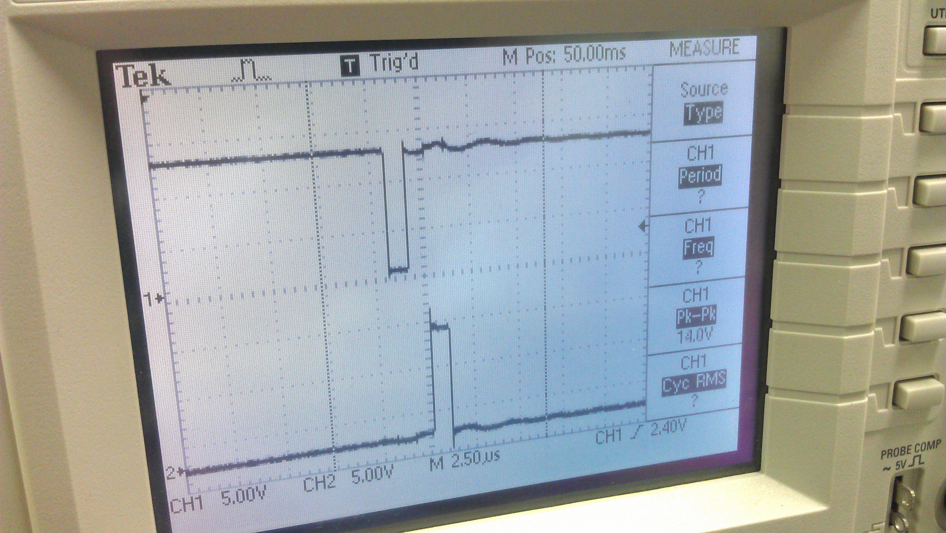
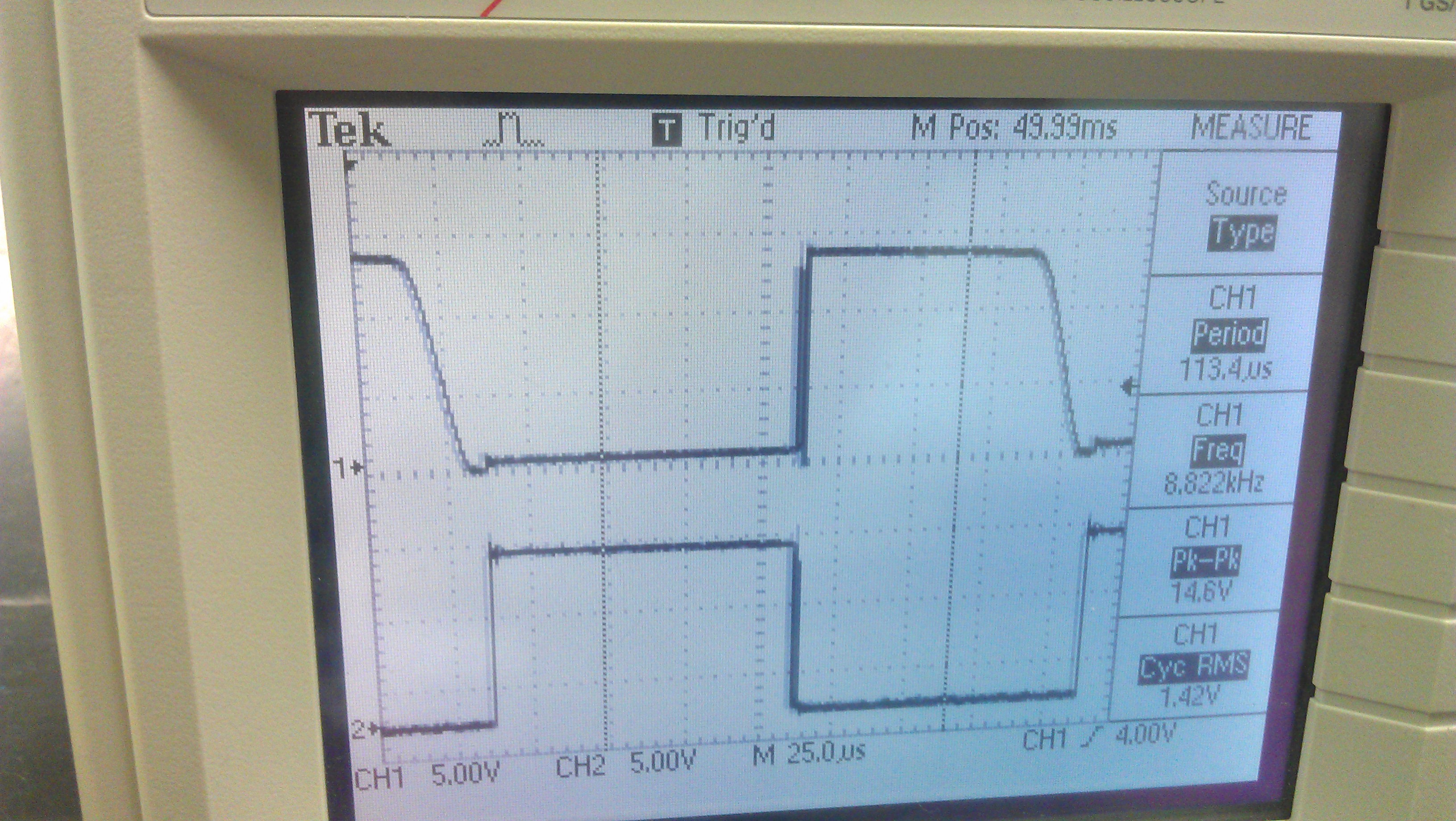
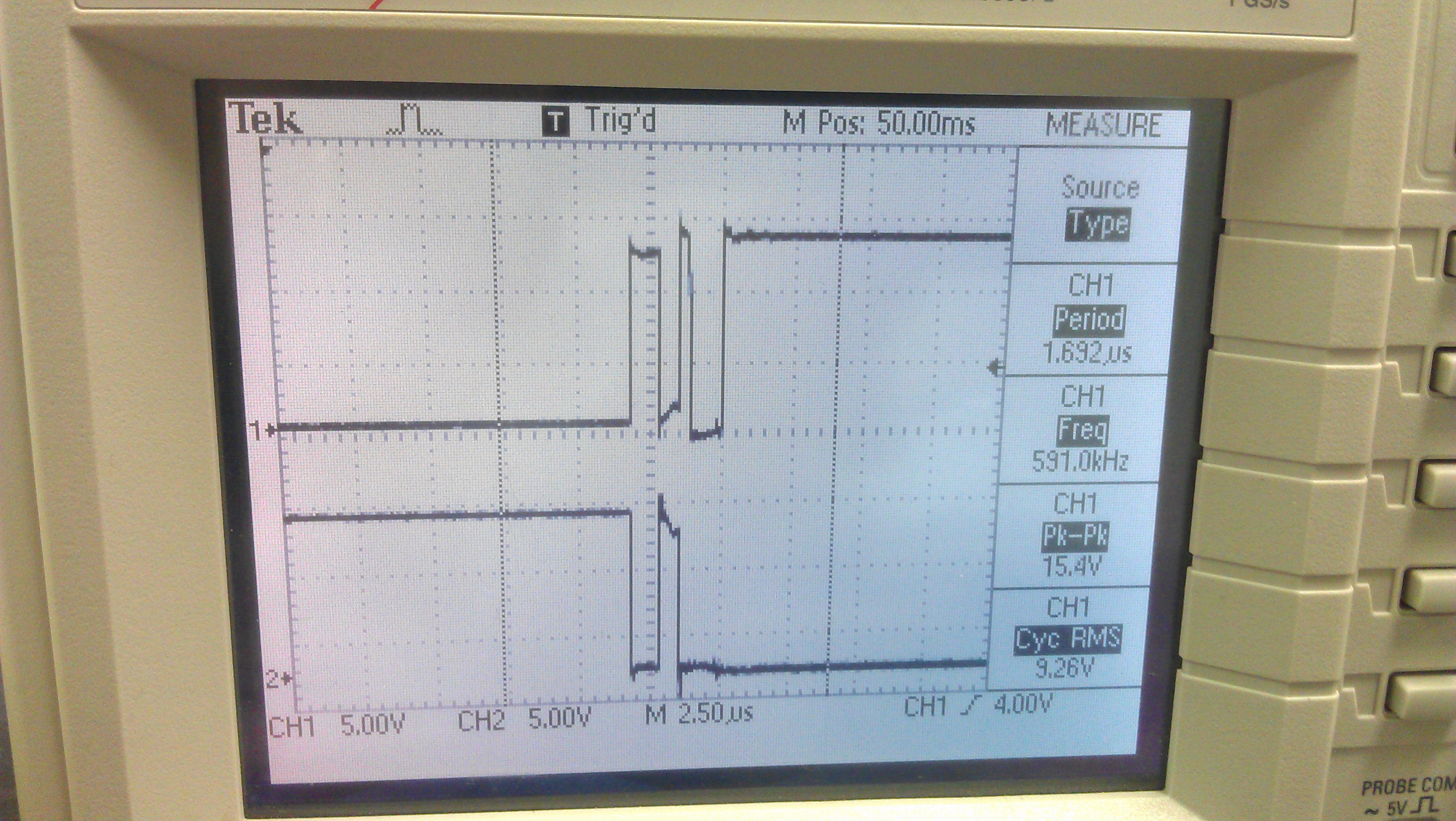
We're using a DRV8432 in a Dual FB, CBC current limit configuration.  We are experiencing problems when we change the current limit resistor.  Originally, we started with a 22k resistor and operations work as expected.  When we try to adjust the CBC with a 47k resistor (we are trying to limit current to around 6A per motor), we see reduced function and sometimes freezing.  We put an scope on the motor ports while the motor was attached, and you can see power on one of the poles start to collapse.  We are running PWM at about 10khz.

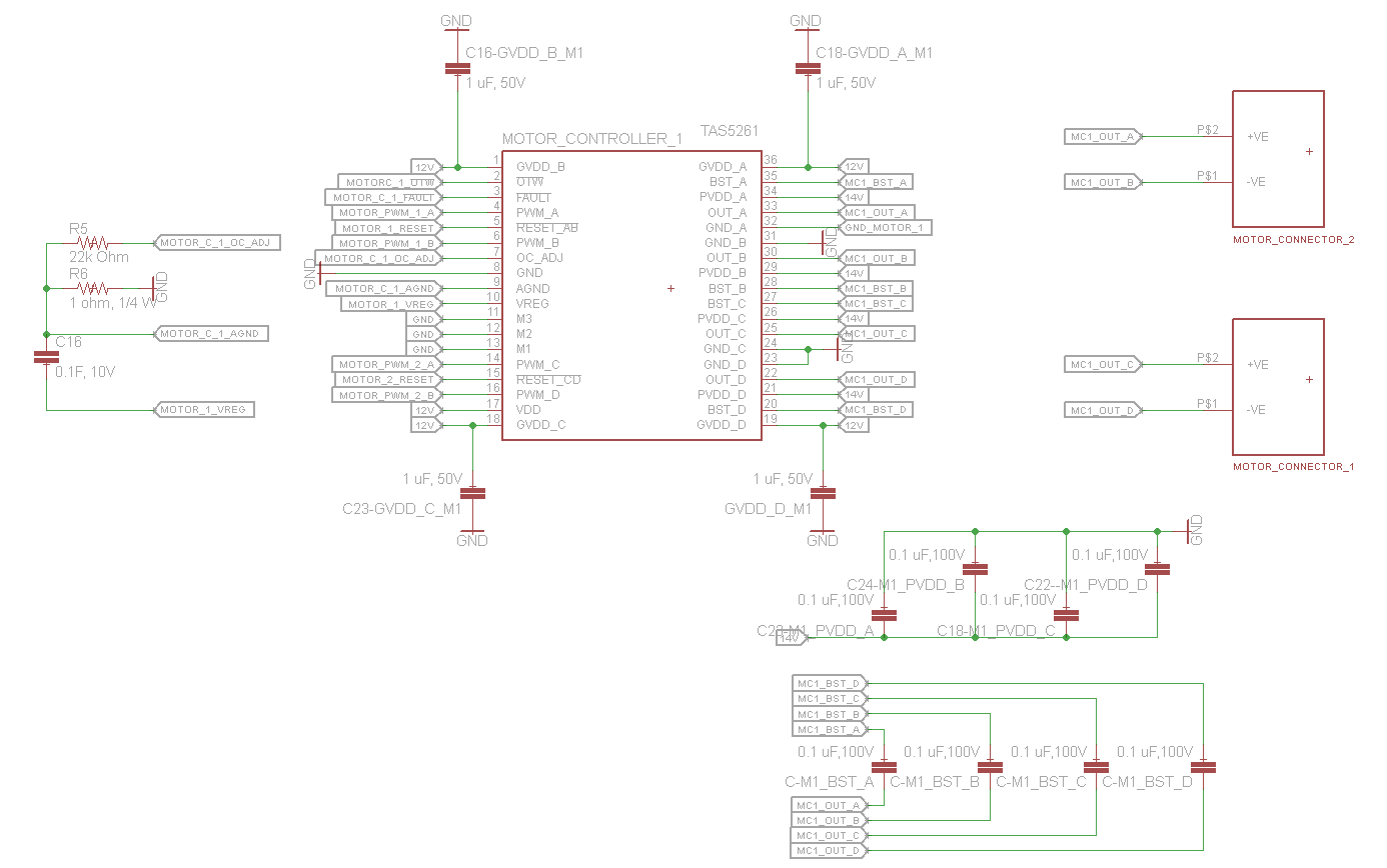
This is our schematic:

And these are some shots from the scope:

  • Hi John

    Not so clear about you issue.

    What do you mean by "freezing"? How about the motor's running behavior when the this happened?

    Could you check the nfault signal also?

    Thanks.

    Wilson

    Motor Application Team

  • Wilson,

    Thanks for the quick reply, I'm sorry to come back so late.  We ran it through a few more tests to try to characterize the failure a little more.  

    First, we've been experimenting with lowering the PWM frequency to try to lower heating on the motor controllers.  This has 

    What we're seeing is that when we drop the PWM frequency below 1.25 kHZ, we start to see jerking motion in the motor.  When running at 10kHz, we have a very smooth motor operation.  When we start to drop the frequency, we see this jerkiness, and in some cases, we see the motor can't start without a push and has very diminished power, or can't start at all.

    Most of the low frequencies work fine with 1.0uF bootstrap capacitors (they totally fail when using 0.1uf bootstrap capacitors), until we start to limit the CBC.  When we add 47k resistors into the limit circuit, we start to see problems going in a certain direction as we lower the PWM frequency.

    I made a very simple excel sheet of our tests; we had a board burn out at very high frequency (159 kHz) and we're not sure if it was a faulty soldering job or related to damage by the board.

    In the table below, "Crash" and "Crash Under Load" means that the microcontroller went unstable for some reason and the system crashed.  

    Original Configuration NEW Configuration
    0.1 uF Caps 1.0 uF Caps
    Resistor Prescaler Freq (kHz) Power M1 M2 M3 M4
    22k 1024 0.3 100% Jerks/Crash Jerks / Crash Fine Fine
    22K 512 0.624 100% Jerks Jerks Crash Under Load Fine
    22K 256 1.25 100% Jerks Crash under Load Fine Fine
    22k 128 2.5 100% Crash Fine Fine Fine
    22K 16 20 100% Fine Fine Fine Fine
    22K 2 159 100% Fine Fine Fine Fine
    47k 1028 0.3 100% Jerks/ Stall Jerks Total Stall / Wont move Total stall / wont move
    47k 512 0.624 100% Jerks / Smooth Jerk / Smooth Total Stall in one direction One direction, goes limp Motor 1 worked well in 1 direction, was jerky in another
    47k 256 1.25 100% Fine Fine One Direction Problems Fine
    47k 128 2.5 100% Jerks Fine One Direction Problems Fine
    47k 16 20 100% Fine Fine One Direction  Fine Suspect Data
    47k 2 159 100% Fine Fine? FIRE! Fine? Danger Zone
  • That table looks really hard to read.  Here's the excel file.  8053.Motor Frequency Testing.xlsx

  • Hi John

    If PWM too low, even lower than the motor phase switching frequency, the driving step may be confused by the PWM and OCP function. then the motor may not get constant torque from one direction.

    Now first you can try start the motor with lower PWM duty, this will reduce the chance that trigger OCP at your already lowered OCP threshold with 47k resistor.

    Second, if you do need low PWM to drive, you can refer to the post http://e2e.ti.com/support/applications/motor_drivers/f/38/p/263135/925259.aspx#925259 including the dealing with LOW pwm that how to select boost cap. DRV8312 and DRV8332 will be mostly alike in the boost strip circuit.

    I really think we can use higher PWM like 20k which make less noise and smooth control. Heat should not a big problem at this condition. of course you need a solid good heat sink even is test.

    About the heat sink, you can refer to one of our part (DRV8432) with simular power and package to DRV8332.

    http://www.ti.com/tool/drv8432evm

    Thanks,

    Wilson

  • Hey Wilson,

    Thanks, I will take a look at the links.

    We're concerned about heat buildup because the chip is going into a sealed plastic enclosure, which we can't run a fan through or let air into.  

    Thank YOU,

    John