This thread has been locked.

If you have a related question, please click the "Ask a related question" button in the top right corner. The newly created question will be automatically linked to this question.

DRV8824 High Frequency STEP signal

Other Parts Discussed in Thread: DRV8824

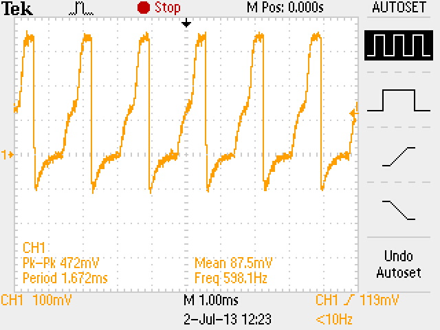
I am trying to implement a circuit using DRV8824 IC which will drive a bipolar motor in microstep mode. The problem arises when the STEP input signal exceeds 600Hz. The output is highly distorted. But the same works just fine for a 100Hz STEP input signal. However my application requires very small pulse duration and therefore I have to work at a higher frequency.

All the connections are as per the data sheet.

Voltages measured are as follows:

VCP=23.4V

VMA=VMB=12.8V

AVREF=BVREF=V3P3OUT=4.01V

DECAY=OPEN

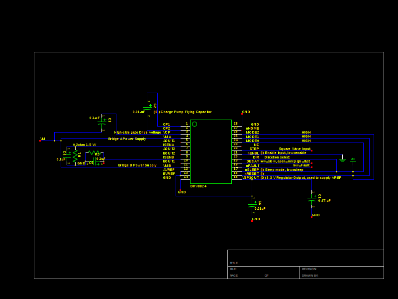
Here is the Schematic:

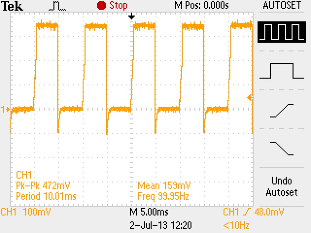
The 100Hz output is as follows:

600Hz output is as follows:

  • Hi Ravi,

    Are you intending to drive this in 32 microstep Step Mode? The input on step only controls the indexer not a direct relation to the output. There are 4 outputs on the chip that will control the stepper through the indexer.

    Also, V303OUT/VREFX should not be exceeding 3.5V according to the datasheet. This makes me think something else is the issue and you are just seeing oscillations from the input on the output pins.

    -Nick

  • Hi Nick,

    Thank you for the quick reply.

    Yes, I intend to drive it in 32 microstep Step mode, for which I have given logic HIGH input on all the three mode pins. I will work with the V3P3OUT/VREFX again and let you know in a short while.

    I appreciate the help. Thank you.

    -Ravi