This thread has been locked.

If you have a related question, please click the "Ask a related question" button in the top right corner. The newly created question will be automatically linked to this question.

DRV8832 faultn behavior

Other Parts Discussed in Thread: DRV8832, DRV8832EVM, DRV8332, DRV8837, DRV8839

Hi, I'm using an DRV8832 to switch a small solenoid back and forth at a rate of 10 Hz.

I use In1, In2 = 0, 0;  1, 0;  0,0;  0,1 ... i.e. standby, fwd, standby, reverse...

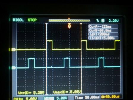
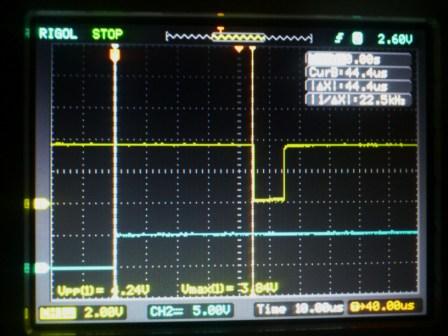
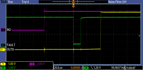
Everytime I switch, the FAULTn signal is asserted for 6 us and this occurs 43 us after IN1 or IN2 is asserted. It doesn't matter if the solenoid is connected to the board or not. The power supply is stable at 5.0 V and the DRV8832 is decoupled with 100 nF. Vref and Vset is connected together. Iref is connected to gnd. FAULTn is pulled up with 1kohm.

The solenoid is switching as expected.

Is this 6 us FAULTn pulse normal behaivor? If not, what can be the problem?

Best regards, Tomas

  • Hi Tomas,

    I do not believe this is normal behavior. It does seem consistent with some type of noise in the system.

    Are you looking at Vcc of the device when you say the power supply is stable? Do you have bulk capacitor on the board (~ 10uF)? You can refer to the EVM schematics for an example.

    Is the 100nF close to the device? 

    How much current are you asking driving in the solenoid?

    Thanks.

  • Thank You Rick for the quick response!

    Vcc was measured with oscilloscope at the 100 nF decoupling capacitor which is placed quite close to the DRV8832, actually in the same position as on the EVM board even if the layout differs somewhat.

    I have in addition to the decoupling capacitor a 1000 uF capacitor with really low ESR (similar to OS-CON type) and a 100 uF low ESR SP-Cap as well. These capacitors are placed 15 - 20 mm away and connected without vias with a trace of decent width.

    The solenoid consumes approximately 200 mA, but that is not the issue here since the 6 us pulse remains unaffected when I disconnect the solenoid from the board and thus the current consumpion should be negligible.

    I have several prototype boards which I can measure on, so now when I know that this behavior is not normal I will continue to measure on another board sample to see if this is individual or systematic and try to make some adjustments to the layout.

    I will report my findings back to you.

    Thanks for the support!

    Best regards, Tomas

  • Hi again.

    I have now purchased an DRV8832EVM evaluation board to which I have feeded the same IN1 and IN2 signals as on my proprietary board. And I can see on the oscilloscope that an identical FAULTn pulse appears on the demo board. So now I start to wonder if my in-pulses are violating any constraint or if the normal behavior of the DRV8832 is to actually drive a short pulse on the FAULTn output when it starts driving?

    Note that the behavior is consistent, it occurs even if the solenoid is not connected and thus the DRV8832 has no load.

    IN1 is a 32 ms positive pulse repeated every 200 ms. IN2 is similar to IN1 but delayed 100 ms in relation to IN1. The voltage levels are 0V and 5V.

    Any ideas?

    Best regards, Tomas

  • Hi Tomas,

    The absolute max ratings on PWM_X and nRESET_X to GND is -0.3V to 4.2V. This may be causing the fault pulse that you are seeing. Can you try with a PWM signal within this range and see if the behavoir is still there.

  • Hi Nicholas,

    Thanks for your reply.

    However I'm afraid you're referring to DRV8332 which have the signals with the names and constraints you are mentioning.

    I use the DRV8832 which doesn't have these signals. My signals which are 0 V and 5 V as described above are applied at IN1 and IN2 inputs.

    And the datasheet revised july 2013 states on page 3 a range of -0.5 V to 7 V on inputs as absolute maximum ratings. http://www.ti.com/lit/ds/symlink/drv8832.pdf

    So I think the generation of the FAULTn pulse must have another cause.

    Any ideas?

    Best regards, Tomas

  • Ah,

    My fault Tomas. I will give this a look and get back to you soon as I can.

  • Tomas,

    Is it possible to get an image of the scope with the inputs and nFAULT next to each other.

  • Hi Nick,

    I'm out of office until monday 19 aug, but you will get the image as soon as I'm back in the lab.

    Thank you and best regards, Tomas

  • Hi again,

    the first picture shows IN1@channel 1 (yellow) and IN2@channel 2(blue).

    The second picture shows FAULTn@channel 1 (yellow) and IN2@channel 2 (blue).

    There is no load on the outputs OUT1 & OUT2.

    Best regards, Tomas

  • Tomas,

    To make sure I have a clear understanding of the setup. I am going to attempt to replicate the error.

    1. TI EVM

    2. No Load

    3. Did you tie ISENSE tied to GND on the EVM?

    4. Does the nFAULT pulse only happen after rising edges on IN1/IN2?

  • Hi Nick,

    1. Yes, I measured on the evaluation module.

    2. Correct, measurement was done with no load. But with/without load doesn't affect the occurrence of the pulse.

    3. Yes.

    4. Did only verify on IN2, but it's always present then. Don't think the direction matters. Absence of pulses results in no pulses from FAULTn (continuously high level).

    Best regards,

    Tomas

  • Thanks for the information Tomas. I will get back to you when I have an answer.

  •  Hi Tomas,

    I have replicated your issue in our lab and am in the process of determining a cause (whether it is layout or design related).

    A few things you can experiment with if you wish to assist.

    Try adjusting the operation voltage, pulse duration, and supply decoupling capacitor and see if the issue persists. I am going to be looking at these things and a few others but it may be a few days before I can get back to you.

  • Hi Tomas,

    Sorry for the delay, but I do have an answer for you.

    This FAULT pulse you are seeing is actually a function of the DRV8832 coming out of its SLEEP state (IN1=0, IN2=0). The FAULT will pulse due to deglitching of the UVLO signal. If you look at the OUT2 signal you will see that it does not assert until after this pulse occurs (see attached scope shot). In general you will never want to hold both outputs low when driving a DC motor which is the reasoning behind this functionality.

    One solution if this delay is not acceptable is to use IN1=1, IN2=1 as you default state and then pulse the inputs low. Alternatively you could find another device that does not utilize this state as a SLEEP state. I will see if I can find a suitable alternative.

  • The DRV8837 or DRV8839 may be a suitable replacements if this behavior is not desired.

  • Thank you for your effort Nick!

    I have verified that by changing the (IN1, IN2) states from (0, 0) to (1, 1) and instead create pulses 1 -> 0 the solenoid will switch just as good as before. And FAULTn is silent. I can quite easily redesign my pulse generating hardware and it will solve my problem. The only drawback is that the current consumption will increase from < 1 uA  in sleep mode to 1,4 mA in operational mode (brake) and my design has a very high focus on low current consumption. Maybe the FAULTn pulse generated when leaving sleep mode should be mentioned in the datasheet?

    However, this will solve my problem. Thank you!

    Best regards, Tomas


  • Glad I could be of assistance. We are currently in the process of getting a datasheet changes submitted.

    Depending on your application it could be possible to put the device into SLEEP mode for periods of non operation and wake it up when you have periods of switching. This way you would only see the pulse when you bring the device out of SLEEP.