This thread has been locked.

If you have a related question, please click the "Ask a related question" button in the top right corner. The newly created question will be automatically linked to this question.

DRV8432 Just doesn't work.....

Hi all,

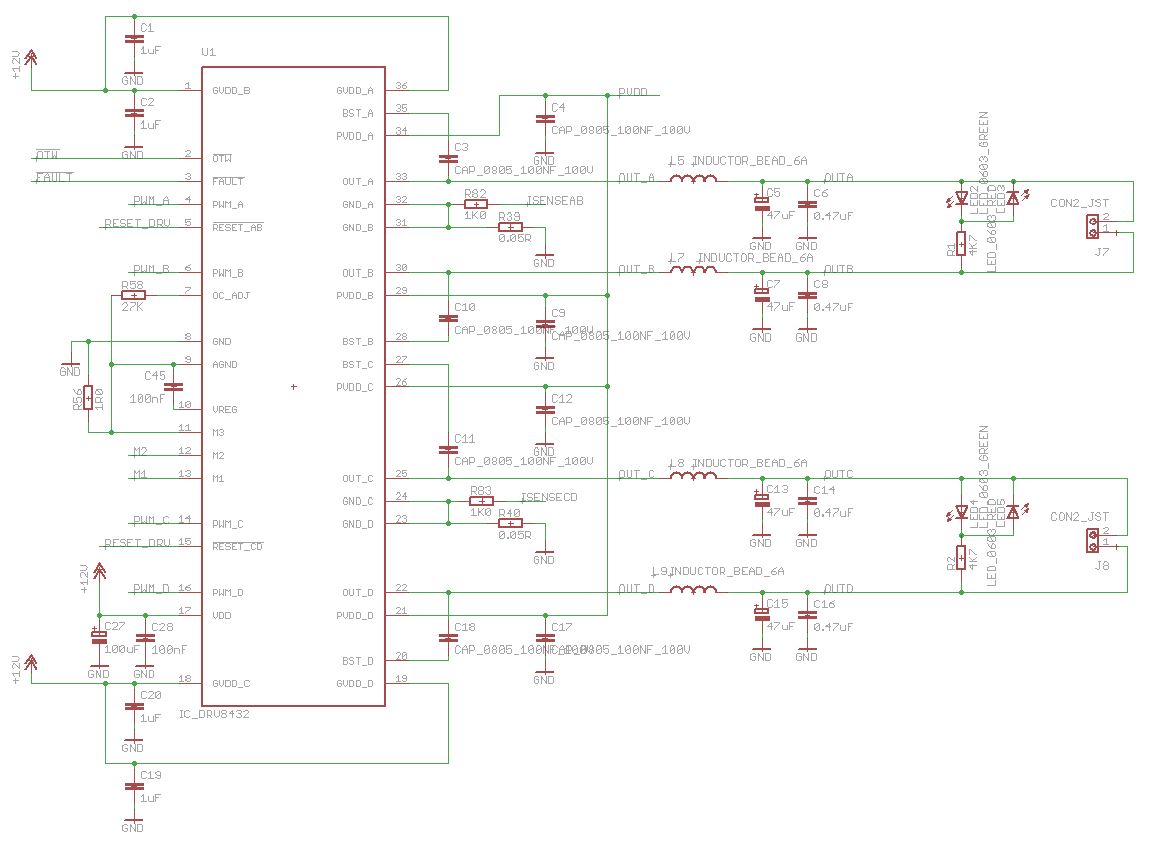
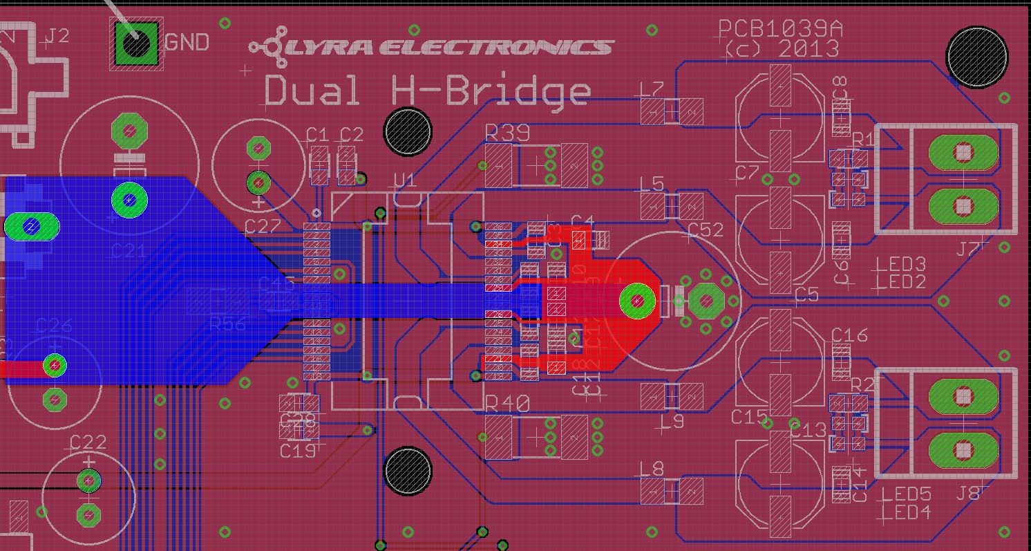
I have copied the EVM schematic and created a PCB to evaluate the DRV8432 in the absence of an evaluation board (below).

The layout of the PCB bears a striking similarity to the EVM board too (why re-invent the wheel?)

The issue I have is that when I start applying a PWM signal the DRV8432 asserts the fault line. The OTP line stays high.
On power-up (in reset) it's fine, take it out of reset and it's fine, but then apply PWM (20kHz) and the fault line is instantly asserted low. This obviously means I've never seen my motor turn.

I am stumped by this. I have tried different frequencies (it was initially 10kHz).

I have tried powering both the 12V and PVDD (18V ) from a linear bench power supply.

I have tried different inductors in the output path.

I have tried with the outputs not connected to any motors at all.

I have replaced the DRV8432 in case I had a faulty one.

All give exactly the same behaviour.

Can anyone help explain this behaviour please? I'm about to give up and use a different device.

Thanks,

Mike

  • Mike,

    A few things that stand out or I am trying to understand. Do you have large decoupling caps on the GVDD and PVDD supplies? What is the purpose of R82/R83 to ISENSE lines? Are you intending to smooth the output with the capacitors (you are driving a DC motor correct)?

  • Hi Nicholas,

    Yes there are large (well, 470uF 50V) electrolytic capacitors, positioned in the same place as on the evaluation board. The PVDD cap is physically close to the middle of the "right" side of the IC.

    The capacitors on the motor outputs were to smooth them, as with the evaluation module, but I've tried the circuit without them too. The circuit behaves the same with or without them.

    R82 and R83 simply go to ADCs  of our controlling processor for monitoring purposes. I've just cut the tracks to these resistors at the 0.05R sense resistors and it has made no difference.

    The layout is attached too for reference. The highlighted section is PVDD.

    Mike

  • Mike,

    Have you tried monitoring PVDD and GVDD on a scope as you apply the PWM signal? Possibly trigger on nFAULT and get a scope shot of PVDD and GVDD. You could also monitor the current with a probe to see if it is spiking when you send the signal. This sort of error seems to lead to some sort of undervoltage or overcurrent problem when you enable the Full Bridges.

  • Mike,

    Another note, in your layout it almost looks like pin 20 and 21 on the DRV8432 are shorting. This could possibly cause the issue you are seeing. Could you check this out.

  • Mike,

    Try removing all of the capacitance after your inductor/bead.  If you look at the schematic in our EVM user guide, we list these as a stuff option for DC output.  If you are switching, you are most likely hitting an OC fault when charging these caps. 

    http://www.ti.com/lit/ug/slou291a/slou291a.pdf

    Figure 3, page 6.


  • Thanks Nicholas - they are not shorting.

  • Thanks Ryan - they are not fitted on this board.

  • Mike,

    Let me know if it is possible to get some scope shots.


  • Hi Nicholas,

    Sorry for the delay - I have been away on business and on holidays.

    This capture shows GVDD (CH1 yellow) and PVDD (CH2 white) against the fault line output (CH3 purple).
    What isn't shown is that the device is taken out of reset 200ns before the fault line activates, with a steady 10% 15kHz PWM signal being applied since power-up.

    The incoming PVDD supply does dip from 24V to 18V, but the 12V GVDD derived from this is pretty good I think.

    Is this PVDD dip enough to trigger a fault?

    Thanks,

    Mike

  • Hi Mike,

    If I am reading the scope shot right it looks like there is about a 1V drop in GVDD right before nFAULT asserts This drop may actually be even worse if the GND is bouncing as well. Is this with no motor connected? That is pretty severe noise on PVDD.

  • There are no motors connected. I have just the inductors on the output lines, and a couple of contra-wired LEDs across the motor connector to indicate motor direction.

    Would you agree that PVDD must be being pulled down by the DRV8432 itself, as it doesn't go anywhere else (other than the 12V supply).

    It is possible that I have a faulty IC?

    This is the second one I've tried, so I'd be surprised if both are faulty.

  • Hey Mike,

    I am having the exact same trouble that you have described. Did you figure out a solution? I am quite desperate to figure this out myself. Else I will just have to replace my controller and see if that helps. I have replaced two drvs already and both show the same behaviour. I do not think that the IC is faulty. 

    Rohit

  • Hi Rohit,

    I had T.I. engineers look over my schematic, and the layout of my PCB in detail.

    We analaysed it over a couple of weeks.

    They could find nothing wrong with either.

    In the end I gave up and used a different part (not from T.I.), which worked first time.


    Sorry I can't be of more help. I'd advise you cut your losses and use a different manufacturer.

  • Thanks Mike. I appreciate your prompt reply. 

  • Hi Rohit,

    Can you share some more details specifically about the issue you are seeing and how you have the device configured? I'd be happy to try and resolve it. We have this device designed into a variety of projects without issue. 

    Things to see would be the schematic, layout, and scope plots of the event occuring (showing the input, output, nfault noctw, pvdd, and gvdd) would be a good first step.

  • I wonder if there's simply insufficient bulk capacitance on PVDD.  The EVM uses 1000uF, versus your 470uF.  With 10V of movement on the power rail shown in the waveform, I would try to make that stable first.

    Best regards,
    RE

  • Hi Nick,

    I simply used a new PCB with the exact same layout. My device is working fine. I am inclined to believe that there was something on my grounding in the old board that must have messed it. I remember the problem started after I exposed it to an undervoltage for an extended span of time. Regardless, everything is fine right now. However, I have noticed that this device is highly sensitive to the way it is grounded. I have always got varying performances with changes in ground. Could you guys specify what is the perfect way to ground this IC?

    P.S I have followed all the basic stuff like linking the PGND and AGND plates at a single point . 

    Cheers,

    Rohit

  • HI RE,

    I have used a capacitor bank of 22400 uF. There is no chance of a drop unless the IC is busted. Regardless, my problem is solved as of now.

    Regards,

    Rohit