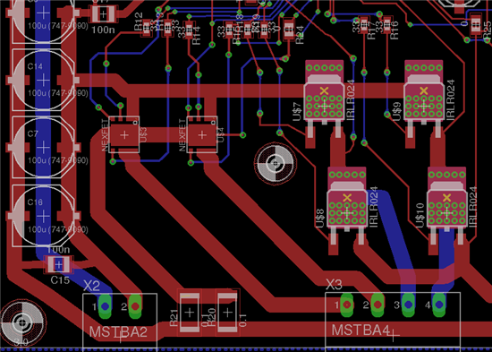
Hi, I have created a board based on the rdk stepper using an lm3s9b96 and two drv8432. Can anyone provide some insight on how to implement fast and slow decay. Thanks
This thread has been locked.
If you have a related question, please click the "Ask a related question" button in the top right corner. The newly created question will be automatically linked to this question.
Hi, I have created a board based on the rdk stepper using an lm3s9b96 and two drv8432. Can anyone provide some insight on how to implement fast and slow decay. Thanks
Hi Anthony
You can refer to DRV8x datasheets for understanding of decay modes.
For basic, try DRV8825, DRV8818.
For advanced, check DRV8711 datasheet.
Thanks,
Wilson
It is my understanding, in order to achieve slow decay, i need to open the high side gates and close the low side. Can this be done with only control of A amd B? Secondly, how would i get fast decay? PWMing the enable? what do i then do with the A and B signals?
thanks
Hi Anthony
Iet me give an example.
If you want to do fast decay,
during PWM_ON time,
Hold PWM_A = 0, PWM_B = 1 (or PWM_A = 1, PWM_B = 0 according to your current direction), nRESET_AB = 1.
during PWM_OFF time,
nRESET_AB = 0. HiZ all output for fast decay. So the PWM is feed to nRESET_AB.
if you want to do slow decay, keep nRESET_AB = 1 all the time.
during PWM_ON time,
Hold PWM_A = 0, PWM_B = 1 (or PWM_A = 1, PWM_B = 0 according to your current direction), nRESET_AB = 1.
during PWM_OFF time,
Hold PWM_A = 0, PWM_B = 0 (or PWM_A = 1, PWM_B = 1 according to high side or low side slow decay). So your PWM is feed to one of the Phase, PWM_A or PWM_B.
Thanks,
Wilson
Motor Appliation Team
Anthony,
There is one more PWM sequence you can follow to get fast decay with DRV8432.
during PWM_ON time,
Hold PWM_A = 0, PWM_B = 1 (or PWM_A = 1, PWM_B = 0 according to your current direction),
During PWM_OFF time
Complement the PWMs i.e.Hold PWM_A=1, PWM_B=0 (or PWM_A=0, PWM_B=1).
RESET_AB signal is always high and not required to for above sequence.
The same logic can be implemented in DRV8432 by selecting mode pins as M3-0, M2-1, M1-1.
Best Regards
Milan
Thanks for the advice, I'm going to try it out. I do have question regarding both solutions, are they going to produce the same results? Is one better than the other? Also, you both said 'during PWM on time hold PWM_x'. When you say hold, do you mean hold 1 or PWM, same for OFF time?
I only have PWM pins mapped to A, B, C, D and my resets are tied to standard GPIO pin (using two of these chips, and only have 8 PWM signals).
Wilson, can you please clarify what you mean by PWM will be fed to the reset?
thanks
Anthony,
Best Regards
Milan- Motor application Team
Will there be a chip like DRV8825(similar functions and pins) with the power of DRV8432?
Giancarlo, to get above 2.5A with similar functionality to the DRV8825, we have the DRV8711.
Best regards,
RE
Excellent, it drives 2 H-bridge(8 n-mosfet)
Are you tested DRV8711 with a NexFET Power Block like CSD87352Q5D (SON 5x6mm)?
Does NexFET Block need external reverse diode to drive 5-10A stepper motor?
Replacing 4 n-mosfet by 2 NexFET Blocks(1H-bridge) i saw a fancy package.
Lacks vias (dissipation) and capacitor, is a draft.
Giancarlo,
The maximum recommended gate voltage for CSD87352Q5D (8V) is lesser than the gate output voltage of DRV8711 (10V typical) so it is not right fit.
You can definitely give try for power block with 20V gate voltage such as CSD87588N with DRV8711. All the synchronous NEXFETs blocks have inbuilt diode so external diode are not required as long as their reverse recovery characteristics does not significantly impact system efficiency and EMI noise performance.
Best Regards
Milan- Motor Application Team
Hi Milan
I would like to review with you FAST Decay in this answer. without using a RESET_AB or CD
PWM_ON , we use a DSP PWM_A = PWMH1 ;PWM_B= PWML1; PWM_C= PWMH2; PWM_D = PWML2.
Let assume we move CW
PWM_A=1, PWM_B=0; PWM_C=1, PWM_D=0;
In our dsp the PWM is set to complementary outpout
PWMH1= PWM= PWM_A
PWML1=PWM=PWM_B
PWMH2= PWM= PWM_C
PWML2=PWM=PWM_D
PWM OFF
when H1 and H2 goes low and L1 and L2 high
the motor does not move short due to a pulse CCW is done
Albert
Sorry I forgot in the previous msg. is any way to have FAST DECAY without using a RESET line
Albert
Albert,
Your PWM logic is correct to achieve fast decay. PWMA and PWM B should be complementary and similarly PWMC and PWMD also should be complementary to achieve fast decay.
In fast decay mode, PWM output is bipolar across H-bridge i.e. output toggles between +VM and –VM so at 50% duty cycle of PWM inputs, output voltage across motor is in fact zero. To rotate motor you should apply duty cycle from 50% to 100% for one direction and 50% to 0 for opposite direction.
Best Regards
Milan-Motor Application Team